Wireless and RF
Modern vehicles expose a surprising amount of attack surface over radio: remote keyless entry, passive keyless entry and start, tire pressure sensors, immobiliser transponders, and more.
Most of these links use simple modulations on unlicensed frequencies and predate any meaningful threat model. Existing research on cryptographic attacks against keyfobs and immobilisers is collected in the Remote Keyless Entry chapter; the existing research on tire pressure sensors and DAB receivers lives in the Other Wireless Attack Surfaces chapter.
This chapter covers the practical side: how the radios that produce these signals are built, which frequencies and modulations to expect, what tooling exists for capture and analysis, and a worked example of decoding a Hitag2 keyfob capture in Universal Radio Hacker.
Radio Architectures
A receiver has to take an antenna voltage of microvolts, select a narrow slice of spectrum, and produce a baseband signal that a digital block can decode. There are three families of receiver worth knowing.
The superheterodyne architecture mixes the antenna signal with a tunable local oscillator (LO) to produce a fixed intermediate frequency (IF). The IF stage does the selectivity work: a sharp crystal or SAW filter at a fixed frequency is far easier to build than a sharp filter that tunes across a wide band. The demodulator then operates on the IF, not the original carrier. Almost every analogue radio receiver built between 1930 and 2000 used this layout, and it remains the default for narrowband receivers today.
Integrated transceiver chips package this entire chain on one die with a digital interface. The TI CC1101 [5] is the canonical example for sub-GHz work: tunable from 300 to 928 MHz, supports OOK, 2-FSK, 4-FSK, GFSK, and MSK with programmable data rates, and exposes a packet engine over SPI. It is the radio inside the Flipper Zero [4]. The YARD Stick One [3] is the same CC1101 silicon but on a USB dongle with open firmware and a Python library (rfcat), so the same captures and replays a Flipper does can be scripted from a laptop. Other common parts in this class are the nRF24L01+ (2.4 GHz, GFSK) and the Silicon Labs Si4432 (sub-GHz).
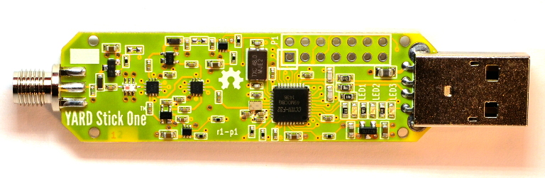 YARD Stick One USB dongle. Photo: Great Scott Gadgets.
Software-defined radios push the digital boundary as close to the antenna as possible. An RTL-SDR [1] is a repurposed DVB-T USB stick (RTL2832U demodulator plus an R820T2 tuner) that streams 8-bit I/Q samples at up to about 2.4 MS/s and tunes from roughly 24 MHz to 1.7 GHz. It is receive-only and costs around €25. If you want to try an SDR before buying one, the University of Twente WebSDR exposes a wideband receiver over the browser.
For transmit, the bladeRF 2.0 micro [2] covers 47 MHz to 6 GHz, full duplex, with a 12-bit ADC/DAC at up to 61.44 MS/s. It sits in the same price range as the older HackRF One but offers full duplex, a wider dynamic range from the deeper bit depth, and a higher sample rate, which makes it the better default if you need to transmit. More capable SDRs (LimeSDR, USRP) trade cost for further increases in sample rate, channel count, clock stability, and bit depth.
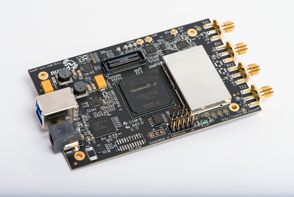 Nuand bladeRF 2.0 micro SDR. Photo: Nuand.
Frequency Bands
Most automotive RF links sit in unlicensed ISM (Industrial, Scientific, Medical) and SRD (Short Range Device) bands. Each region's regulator (ETSI EN 300 220 in Europe [13], FCC Part 15 in the United States [14], ARIB in Japan) defines a power limit and, often, a duty-cycle limit per band. The bands relevant to automotive work are:
| Band | Region | Typical use |
|---|---|---|
| 125 kHz / 134 kHz | Worldwide LF | Immobiliser transponders, PKES wakeup, RFID |
| 13.56 MHz | Worldwide HF | NFC keycards, some immobiliser systems |
| 315 MHz | North America, Japan | Keyfobs, TPMS |
| 433.05 to 434.79 MHz | Europe, Asia | Keyfobs, garage doors, TPMS |
| 868 to 868.6 MHz | Europe SRD | Keyfobs |
| 902 to 928 MHz | North America ISM | Keyfobs |
| 2.4 GHz | Worldwide ISM | Bluetooth Low Energy, WiFi |
Modulation
Once the receiver has isolated the right slice of spectrum, the modulation determines how bits ride on the carrier.
Amplitude Shift Keying (ASK / OOK)
The simplest modulation: a "1" is the carrier present, a "0" is the carrier absent (or at a lower amplitude). Also called OOK (on-off keying). ASK is cheap to generate (a single transistor switching the oscillator on and off) and cheap to demodulate (a diode envelope detector). It dominates older keyfobs and TPMS sensors in the 315/433 MHz bands.
Amplitude Shift Keying (ASK / OOK)
The bit rate is set by the digital signal above. The carrier frequency is independent — slide it down to see a single cycle (or less) per bit, and up to see many. Demodulation only needs the envelope, not a fixed cycle count.
Frequency Shift Keying (FSK)
FSK keeps the amplitude constant and switches the carrier between two frequencies, one for "0" and one for "1". FSK decoding tolerates amplitude changes due to external influences. It is the default modulation for modern keyfobs.
Frequency Shift Keying (FSK)
FSK keeps the amplitude constant and swaps the carrier frequency between two values. Larger deviation is easier to demodulate but uses more bandwidth.
Binary Phase Shift Keying (BPSK)
BPSK keeps both the amplitude and frequency constant, and encodes bits as 180° phase shifts of the carrier. It is rare on cheap links because it requires a coherent reference at the receiver, but it appears in higher-end protocols (some PEPS systems, parts of C-V2X). The same chips that do BPSK also extend to QPSK, 8-PSK, and QAM for higher data rates.
Binary Phase Shift Keying (BPSK)
Each bit transition flips the carrier phase by 180°. Receivers recover the bitstream by comparing phase against a reference (coherent BPSK) or by detecting the discontinuity (differential BPSK).
Manchester Line Coding
When transmitting RF data, no separate clock signal can be included, and we cannot rely on the transmitter's and receiver's clocks to stay in sync. The clock and data therefore have to be combined into the same signal.
Manchester coding solves this problem by splitting each bit period into two halves and forcing a transition in the middle. The direction of the transition carries the bit. Two conventions are in use, and they are exact inverses of each other:
- Manchester I (also called G.E. Thomas):
1is a falling edge mid-bit (high then low).0is a rising edge (low then high). - Manchester II (also called IEEE 802.3):
1is a rising edge mid-bit.0is a falling edge.
Manchester Line Coding
Manchester guarantees a transition in every bit period, which carries the clock alongside the data. The two conventions are inverses of each other — a decoder locked to the wrong one produces the complement of the original bitstream.
Manchester doubles the symbol rate compared to NRZ for the same data rate, in exchange for a guaranteed transition every bit. A decoder locked to the wrong convention produces the bitwise complement of the original stream, which is the first thing to try when a captured frame looks almost-but-not-quite right. Differential Manchester (used in some token-ring and industrial protocols) is a variant where the bit is encoded by the presence or absence of a transition at the bit boundary, making it polarity-independent.
Software
A handful of tools cover the majority of practical RF reverse engineering work.
Gqrx, SDR++, and SDR#
Gqrx [8], SDR++ [9], and SDR# [10] are general-purpose receivers with a waterfall display. They are the right starting point for any new signal: tune around the expected frequency, press a keyfob button, see whether a burst appears in the waterfall, eyeball the bandwidth and the modulation family.
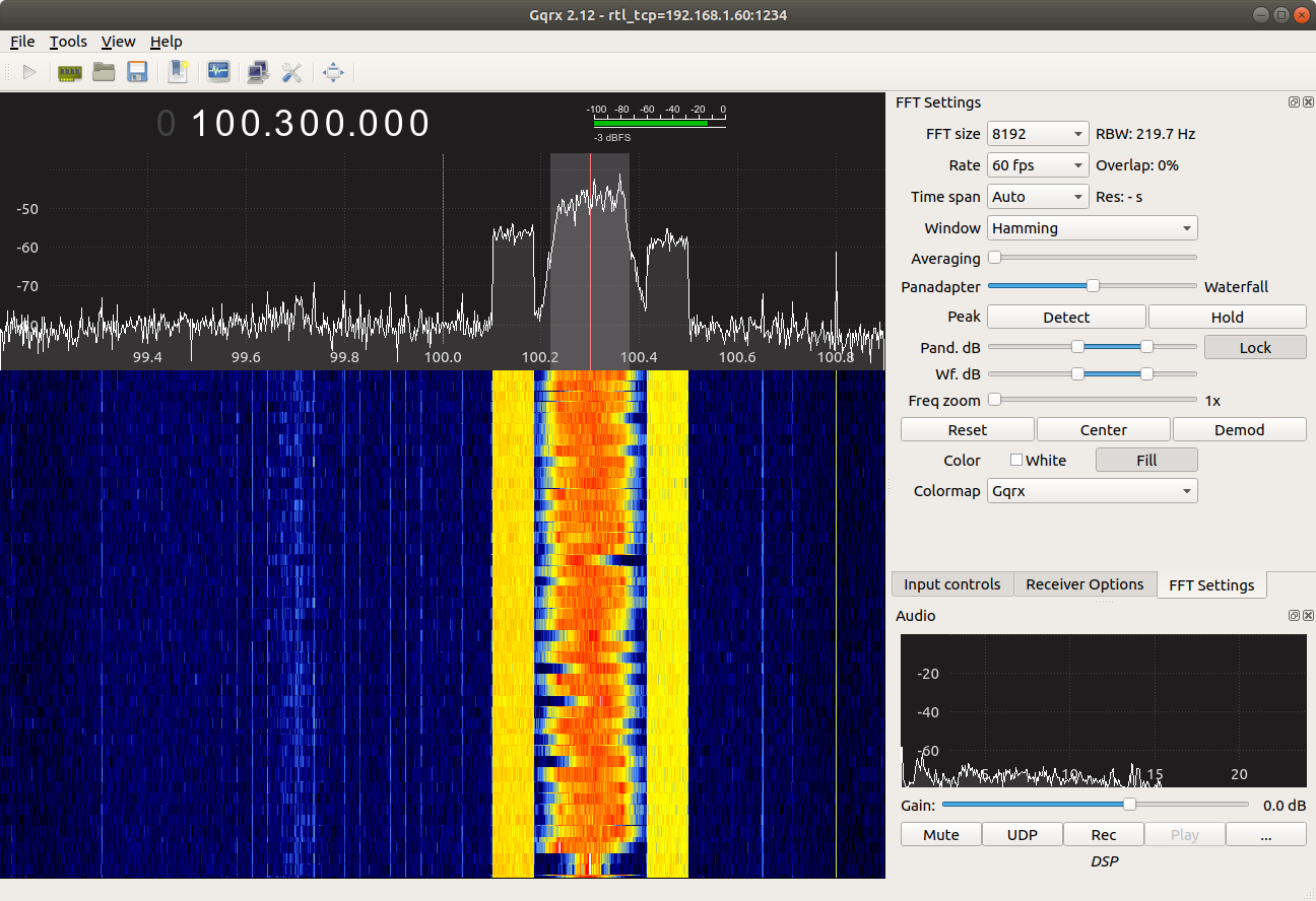 Gqrx waterfall display
GNU Radio
GNU Radio [7] is the underlying DSP framework. Its graphical editor (GNU Radio Companion) lets you wire up signal-processing blocks into a flowgraph. Use it when you need a custom demodulator, a non-standard symbol rate, or any kind of bespoke signal processing that the other tools in this list do not handle.
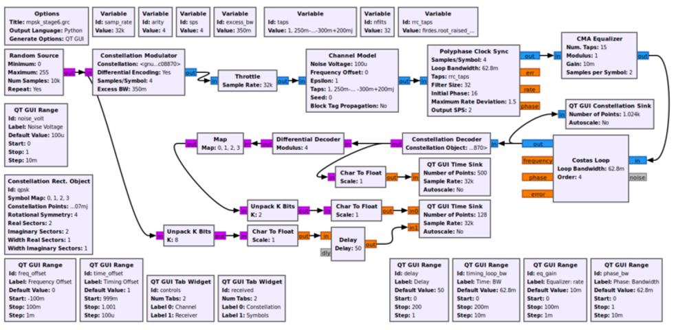 GNU Radio Companion flowgraph.
CyberEther
CyberEther [11] is a GPU-accelerated DSP and visualization framework. The blocks-and-wires editing model is similar to GNU Radio Companion, but the runtime targets the GPU (Metal, Vulkan, CUDA) instead of the CPU, which lets it draw waterfalls and run filters on wider bandwidths than GNU Radio can without dropping samples.
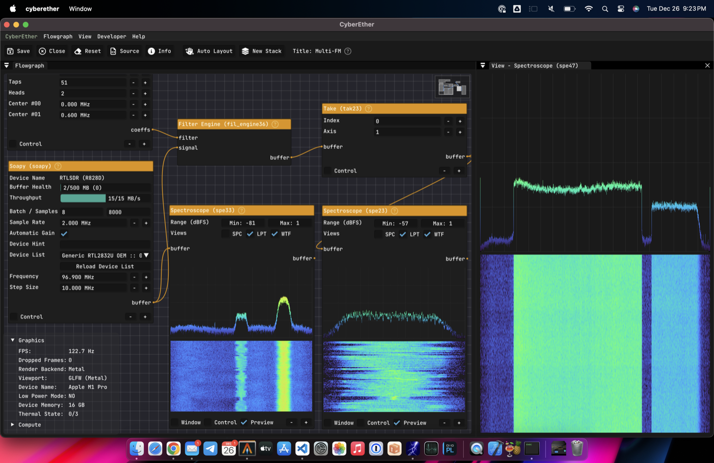 CyberEther interface. Image: Luigi Cruz / CyberEther.
Universal Radio Hacker
Universal Radio Hacker (URH) [6] covers most of what replay-style attacks on simple protocols need. It records to file, lets you slice bursts out of a long capture, has built-in demodulators for ASK/FSK/PSK, line decoders including Manchester, an analysis tab that aligns bits across multiple captures and highlights what changed, and a transmit path that drives any supported SDR.
 URH decoding the data from a TPMS sensor
rtl_433
rtl_433 [12] is a decoder for known ISM-band protocols: weather sensors, TPMS sensors, energy meters, and many consumer doorbells and remotes. Run it before anything else. If rtl_433 already recognises the signal, you save yourself the work of demodulating from scratch and you get a documented packet layout for free.
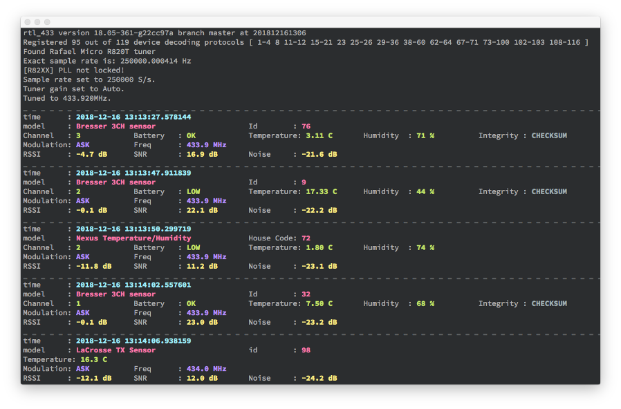 rtl_433 decoding several ISM-band sensors. Image: merbanan/rtl_433.
Tutorial: Decoding a Hitag2 Keyfob in URH
Hitag2 is a transponder protocol used in immobilisers and unidirectional RKE. The cryptographic weaknesses are documented in the Remote Keyless Entry chapter; this tutorial only covers the layer below: how to capture a button press and locate the rolling counter in the resulting bitstream. The capture is from a 433.92 MHz European keyfob.
Record the Signal
URH has a built-in recorder. Open File, Record signal, pick the SDR backend, set the centre frequency to 433.92 MHz, the sample rate to 1 MS/s. Press Start and then press the lock button on the keyfob several times. The rolling counter will increment between presses, which is what makes the counter visible later. Stop the recording and save it to a .complex file. A short burst per press should appear in the waterfall, lasting roughly 20 to 80 ms depending on the manufacturer.
Open the recording in URH's Interpretation tab. The burst is visible as a packet of amplitude transitions sitting above the noise floor.
 URH interpretation view with a recorded Hitag2 burst, amplitude axis.
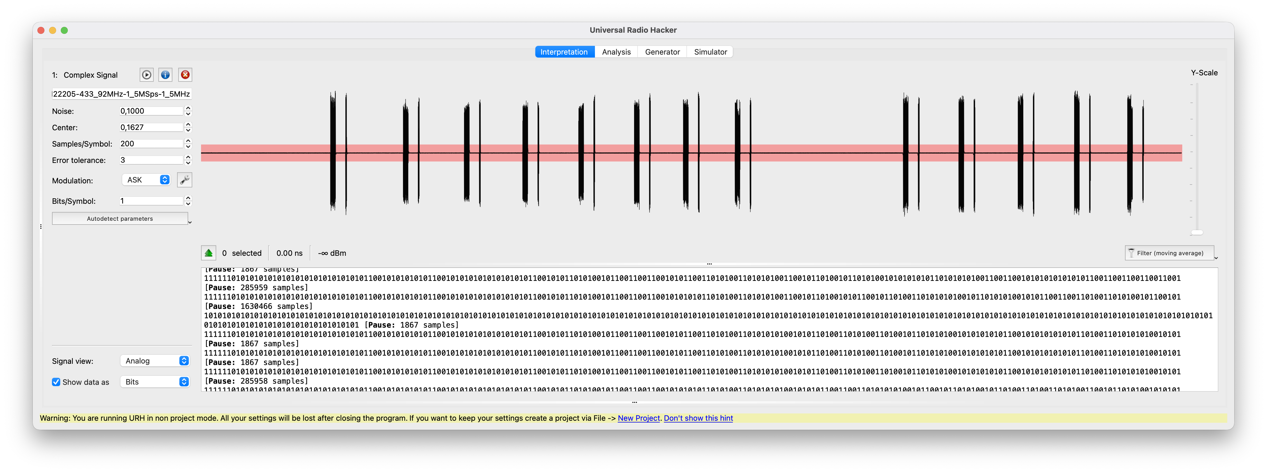
Demodulate and Recover the Symbol Rate
Hitag2 RKE frames are ASK with Manchester line coding. Set the modulation to ASK in the modulation panel. Zoom in, and select a single bit to determine the length. Set this in the samples/symbol field. Also make sure the noise value is set up appropriately.
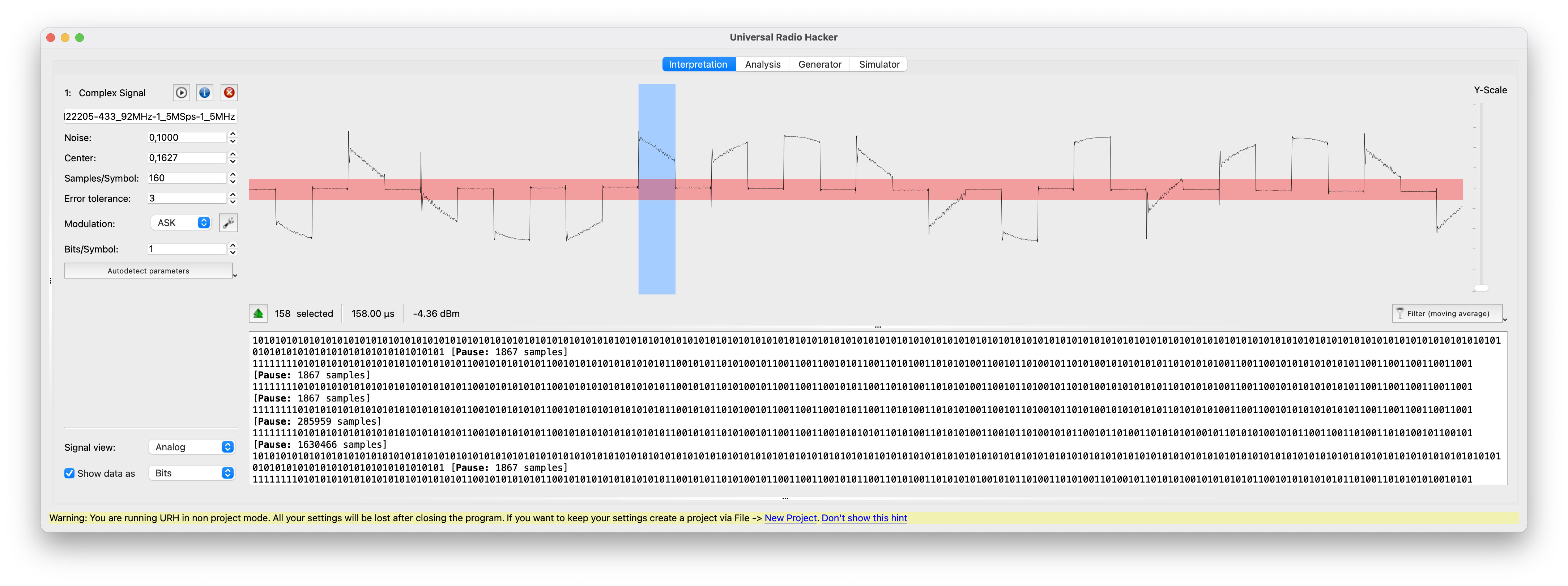 URH modulation panel with ASK selected and the auto-detected bit length highlighted.
Apply Manchester Decoding
Switch to the Analysis tab. Create a new decoding chain that applies Manchester I or Manchester II. In the next stage we will identify the rolling counter. If it decreases instead of incrementing, change from Manchester I to II or vice versa.
The decoded frame should be on the order of 64 to 128 bits including preamble and sync.
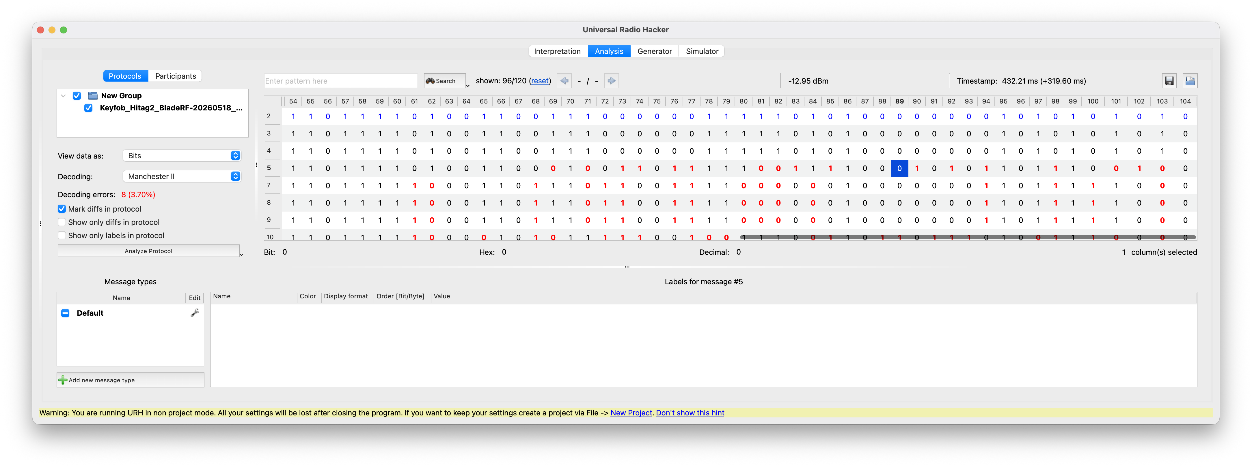 URH analysis tab showing several aligned frames after Manchester decoding.
Find the Rolling Counter
Line several decoded frames up in the analysis view. Most of the bits are identical across captures: the UID, the button code, and fixed framing fields do not change. The bits that do change come from two places:
- The rolling counter, which increments by one (or a small fixed amount) every button press.
- The MAC, which depends on the counter and the secret key, and therefore looks random.
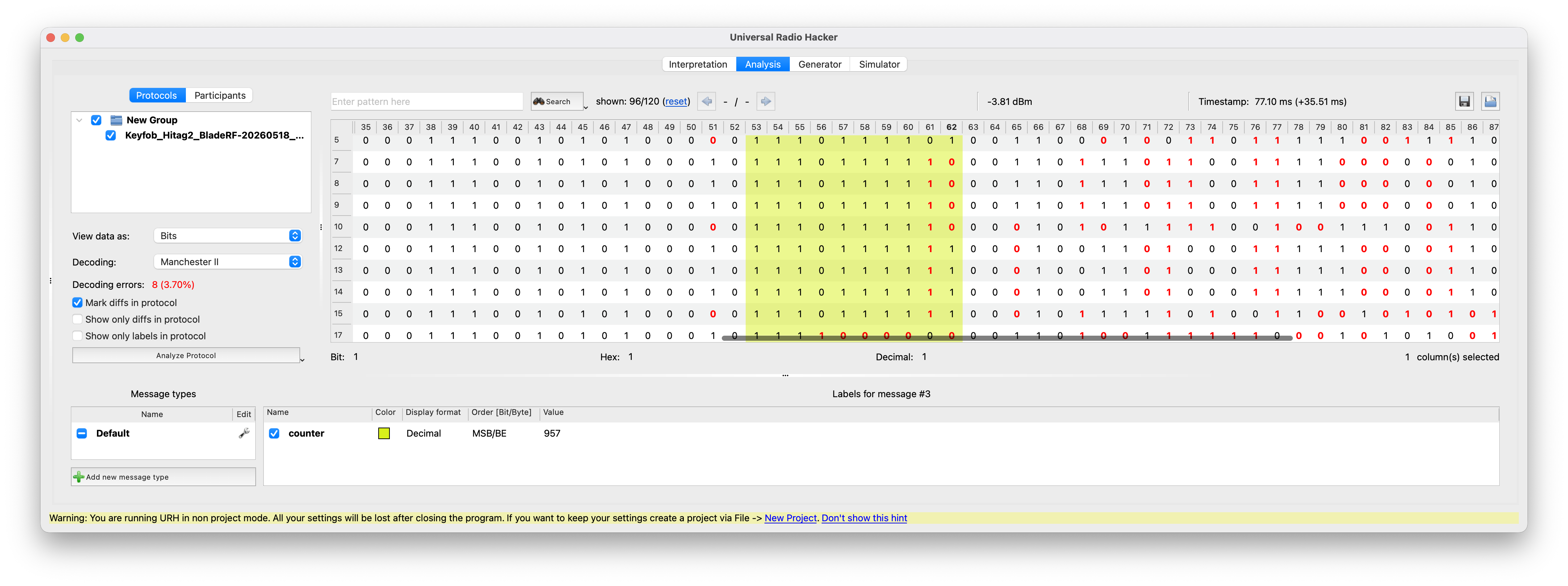
Sort the captures by press order. The counter shows up as a small contiguous block of bits that increments monotonically, with the low bits flipping most often. URH highlights changing bits per column, which makes this immediately visible.
 URH analysis view with bit-level diff colouring across five captured frames; the counter region is the small cluster of changing bits on the left of the MAC.
Align with the Frame Layout
Once the counter is located, the rest of the frame falls into place by alignment. The Hitag2 RKE frame layout is published in the existing-research papers referenced from the Remote Keyless Entry chapter:
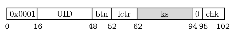 Hitag2 RKE frame layout showing the 102-bit packet structure: preamble, UID, button code, low-order counter bits (lctr), keystream (ks), padding, and checksum. Figure from Garcia et al., 2016 (Lock It and Still Lose It).
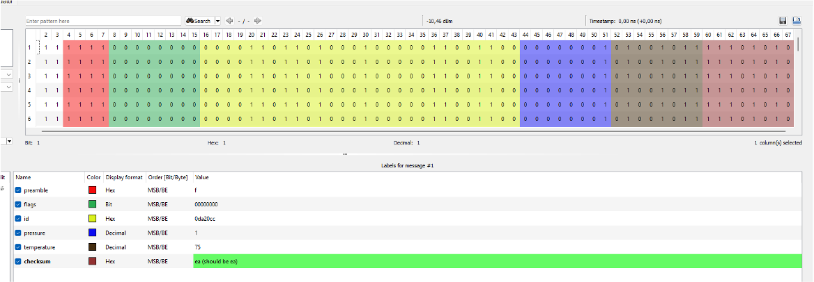
Mark each region in URH's Label view to confirm the alignment is consistent across captures. The UID, button, and counter fields should be byte-aligned and stable in the expected way; the MAC region should differ in every frame.
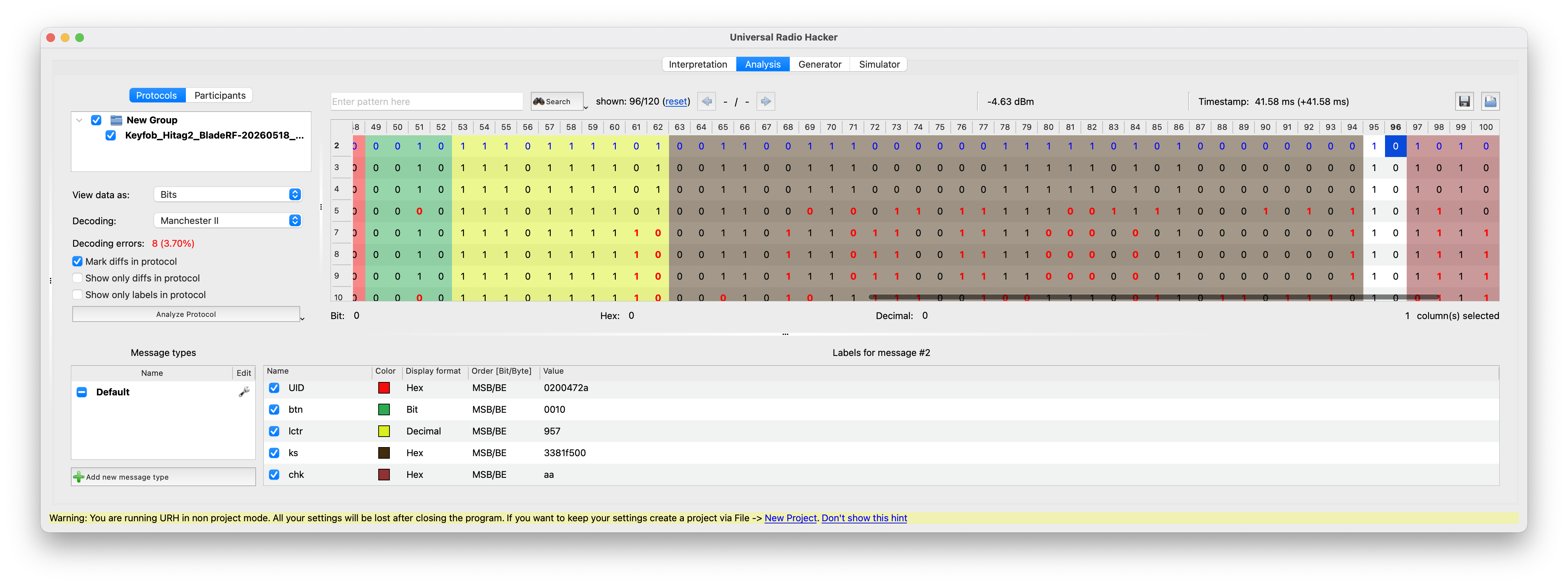 URH labels assigned to the UID, button, counter, and MAC regions of the decoded frame.
At this point you have a fully labelled frame: every bit on the air is accounted for, and a replay attack on a captured frame is one click away. The MAC is what stops a straight replay from working in practice, because the receiver tracks the counter and rejects anything that does not advance it. Breaking the MAC requires recovering the Hitag2 key, which is what the cryptographic attacks in the existing-research chapter do.
FSK Decoding on Noisy Captures
For FSK, URH demodulates the signal by tracking whether the instantaneous frequency is above or below the configured centre. This works well when the two tones are clean, but broadband noise or a nearby carrier can cause the demodulator to cross the threshold at the wrong time and produce unstable bits.
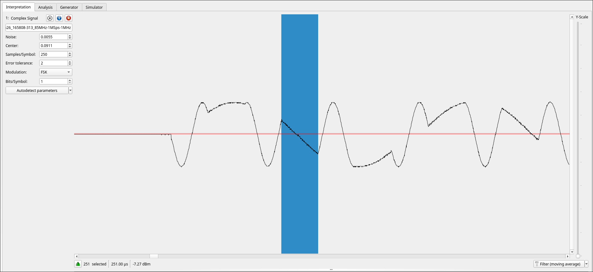 FSK in URH's analog view: the two bit values appear as distinct frequencies, with one lower-frequency bit highlighted.
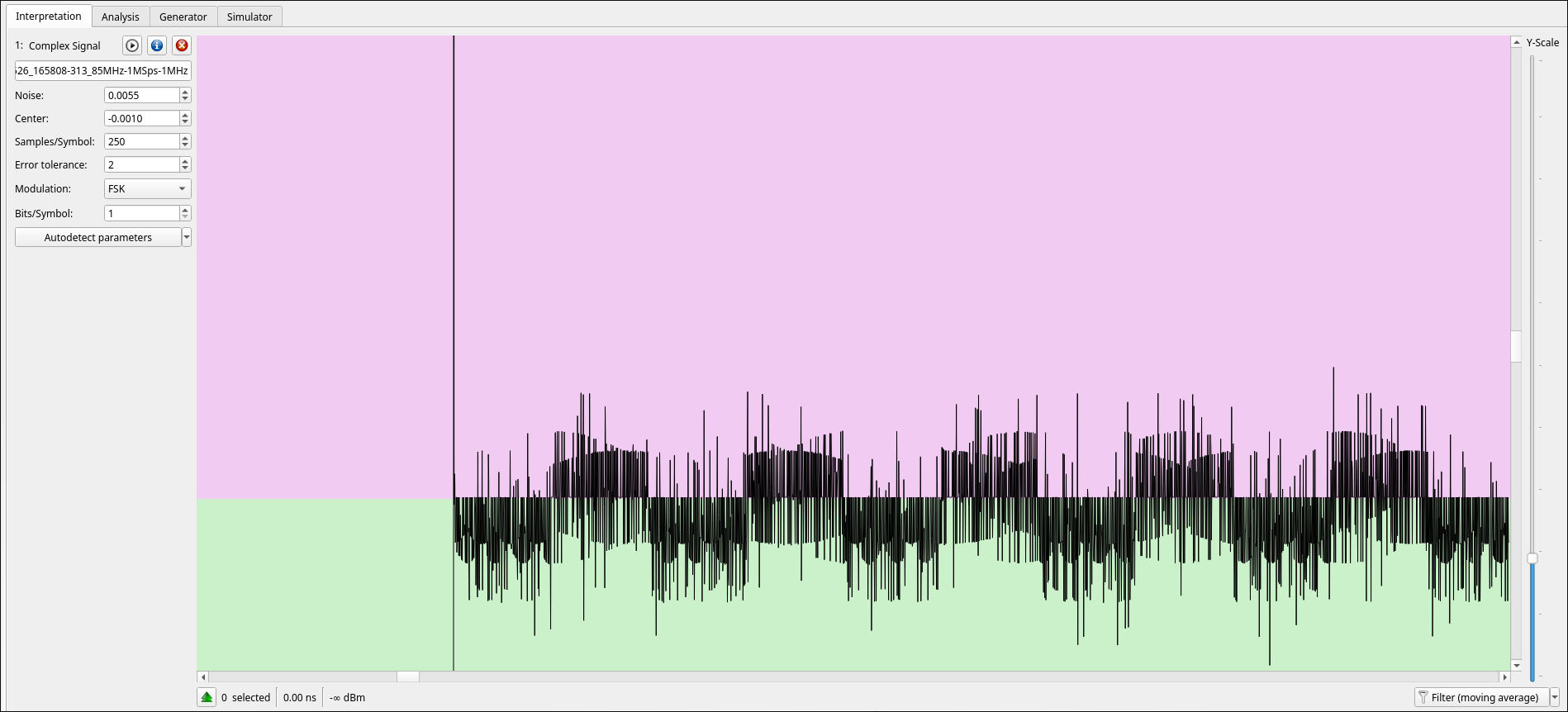 Noisy FSK demodulation in URH: the frequency trace crosses the decision threshold repeatedly, making symbol decisions unreliable.
To clean the signal and ensure it decodes properly, switch the signal view to Spectrogram, select only the occupied FSK channel, then right-click and choose Apply bandpass filter. The selection should include both FSK tones and a small guard band. If the band is too wide, the noise remains; if it is too narrow, one tone is attenuated and the bit stream is distorted.
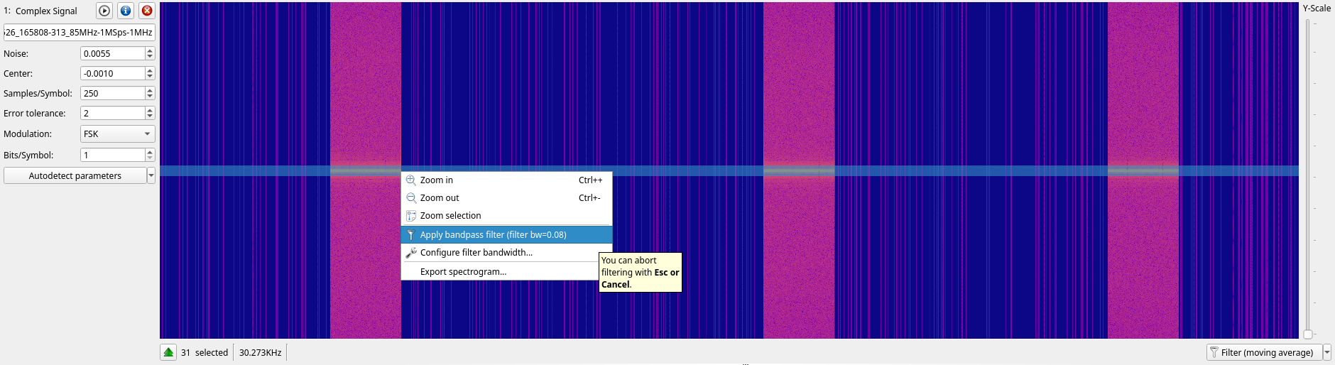 Applying URH's bandpass filter around the occupied FSK channel in the spectrogram view.
URH creates a filtered copy of the signal. Demodulate that copy with FSK, then re-check the centre, noise threshold, and samples-per-symbol. The filtered trace should have two stable levels with far fewer threshold crossings, making the recovered bits repeatable across bursts.
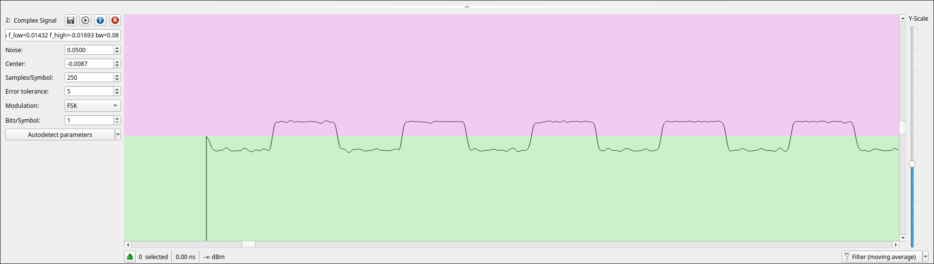 The same FSK capture after bandpass filtering: the demodulated trace has clean high and low frequency levels.