Vehicle Documentation
Manufacturer Documentation
The Electrical Wiring Diagram (EWD) or diagnostic software for many cars can be found online for a small payment. These are usually provided to consumers to comply with the US Right to Repair or Euro 5 regulations.
Prices last checked: May 6, 2026. Some portals only show exact prices after registration, login, country selection, or purchase flow.
| Manufacturer | Service | Pricing | URL |
|---|---|---|---|
| ALLDATA | Wiring diagrams for many makes | DIY $19.99 / 1 mo; Repair $209/mo | alldata.com |
| BMW (EU) | Aftersales Online System | — | aos.bmwgroup.com |
| BMW (US) | Technical Information System | $32/day, $270/mo | bmwtechinfo.bmwgroup.com |
| Ford | Ford Service Info | US all-lines $2,834.95/yr | fordserviceinfo.com |
| Genesis (US) | GenesisTechInfo | $100 / 7 days, $250/mo | genesistechinfo.com |
| GM | Technical Delivery System | $22 / 3 days, $168/mo | acdelcotds.com |
| Honda (EU) | MaRIS | €10/hr, €30/day | techinfo.honda-eu.com |
| Honda (US) | Independent Repair Website | $20 / 3 days, $50/mo | techinfo.honda.com |
| Hyundai (EU) | Global Service Way | — | service.hyundai-motor.com |
| Hyundai (US) | HyundaiTechInfo | $40 / 7 days, $60/mo | hyundaitechinfo.com |
| Kia (EU) | Kia Global Service Way | — | kia-hotline.com |
| Kia (US) | KGIS | $19 / 72 hr, $150/mo | kiatechinfo.snapon.com |
| Land Rover | TOPIx | €80/hr, €131/day (all docs) | topix.landrover.jlrext.com |
| Lexus (EU) | TechDoc | — | lexus-tech.eu |
| Mercedes-Benz | XENTRY WIS | $75/day, $395/mo | startekinfo.com |
| Nissan (US) | Techinfo | $35/day, $135/mo | nissan-techinfo.com |
| PSA Group | Service Box | Peugeot €5.20/hr, €23/day | public.servicebox.peugeot.com |
| Renault | After Sales Subscription | — | asos.renault.com |
| Stellantis | Mopar Technical Information | — | technicalinformation.fiat.com |
| Subaru (US) | STIS | $34.95 / 3 days, $299.95/mo | techinfo.subaru.com |
| Toyota (EU) | TechDoc | — | toyota-tech.eu |
| Toyota (US) | Toyota Techinfo | $30 / 2 days, $105/mo | techinfo.toyota.com |
| Volkswagen Group | erWin | €8.40/hr, €36/day | volkswagen.erwin-store.com |
| Volvo (EU) | TIS | — | tis.volvocars.biz |
| Volvo (US) | VIDA | Parts+service $21.04 / 3 days; full $73.14 / 3 days | volvotechinfo.com |
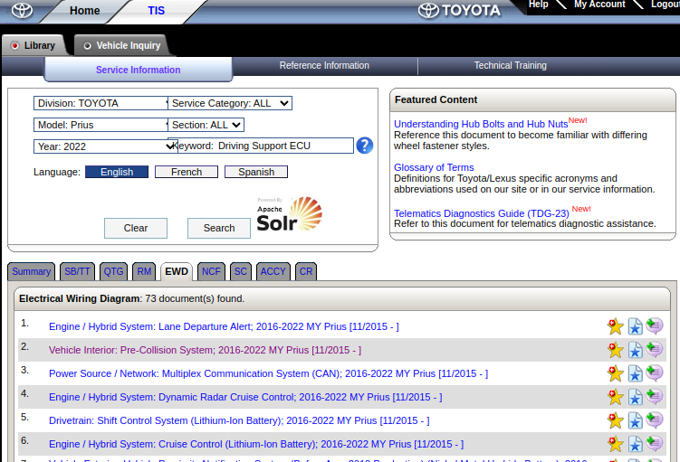 Toyota Technical Information System (TIS)
J2534 Passthrough Device
J2534 is a standard for talking to USB-to-CAN adapters for reprogramming ECUs. It's required for car manufacturers to allow consumers or independent mechanics to flash ECU updates for emissions purposes using J2534. A manufacturer of a CAN adapter will usually provide a J2534-compatible .dll for their adapter.
As part of the subscription, a diagnostic program can usually be downloaded that can interface with the vehicle through a J2534-compatible adapter. However, sometimes this software is limited in functionality compared to an OEM scan tool or tablet.
Checking how the manufacturer software interacts with the car can provide valuable information and can allow firmware files to be obtained by observing the reflash over CAN. This can be done by connecting a second CAN adapter on the bus, or by using a special logging or sniffing J2534 DLL, which passes through all communication to the device, but also logs to a file.
Types of Diagrams
There are usually a few different types of diagrams available. Not every manufacturer will provide all of them, but it's good to know what kinds of diagrams exist.
Wiring Diagram
The most common diagram is the Electrical Wiring Diagram (EWD). It shows the wiring between an ECU and various components, along with the connectors and pin numbers. Note that an ECU is usually broken up into different parts of the schematic and might be spread out over multiple pages where different pins are shown on each page. Specific ECUs or connectors often have a letter/number combination as well, and those might even be reused across different car models from the same manufacturer.
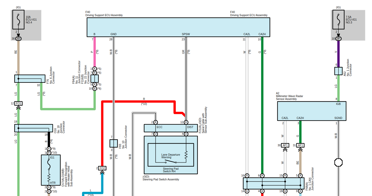 Example wiring diagram showing the Driving Support ECU on a Toyota Prius.
CAN Bus Diagram
Another useful diagram is one that shows everything that's connected to a specific CAN bus. The diagram below shows one of the ADAS CAN buses on a Kia EV6, connecting the four corner radars. This kind of diagram helps you figure out the best spot to tap a CAN bus. In this case the radars are on the outside of the car, but the bus is routed through the interior and can be accessed at the Joint Connector JF01.
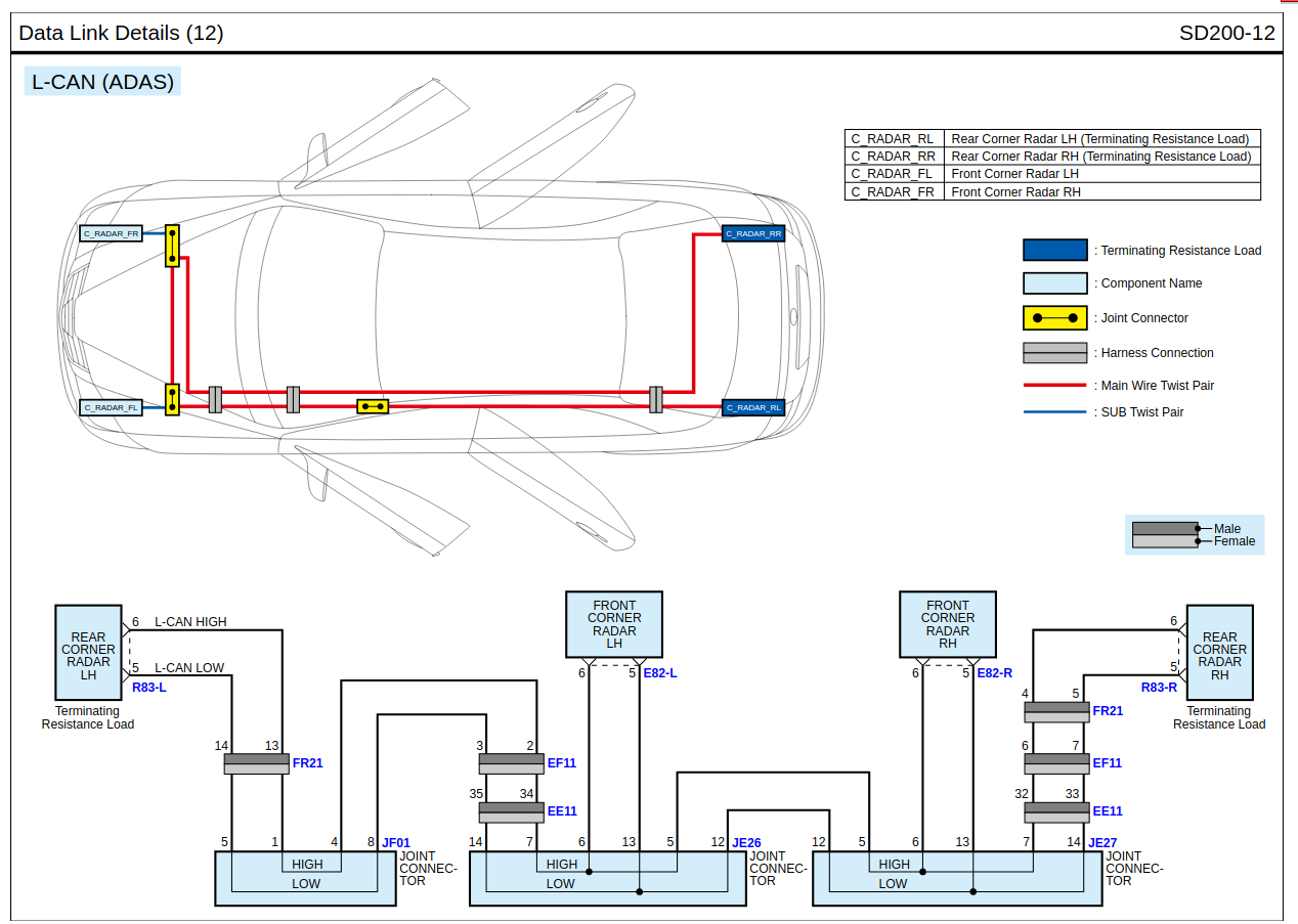 Example of a diagram showing how a CAN bus is wired across the vehicle and which components are connected to it. Diagram from a Kia EV6.
Connector Location and Pinout
From the wiring diagram it's often possible to click through to the connector pinout of the specific part. Sometimes these can be found in a dedicated list of connectors. If an ECU has multiple connectors, sometimes there is a diagram that shows the location of each individual connector. Otherwise you have to match the right connector based on the number of pins, coloring of the wires, or the shape of the connector.
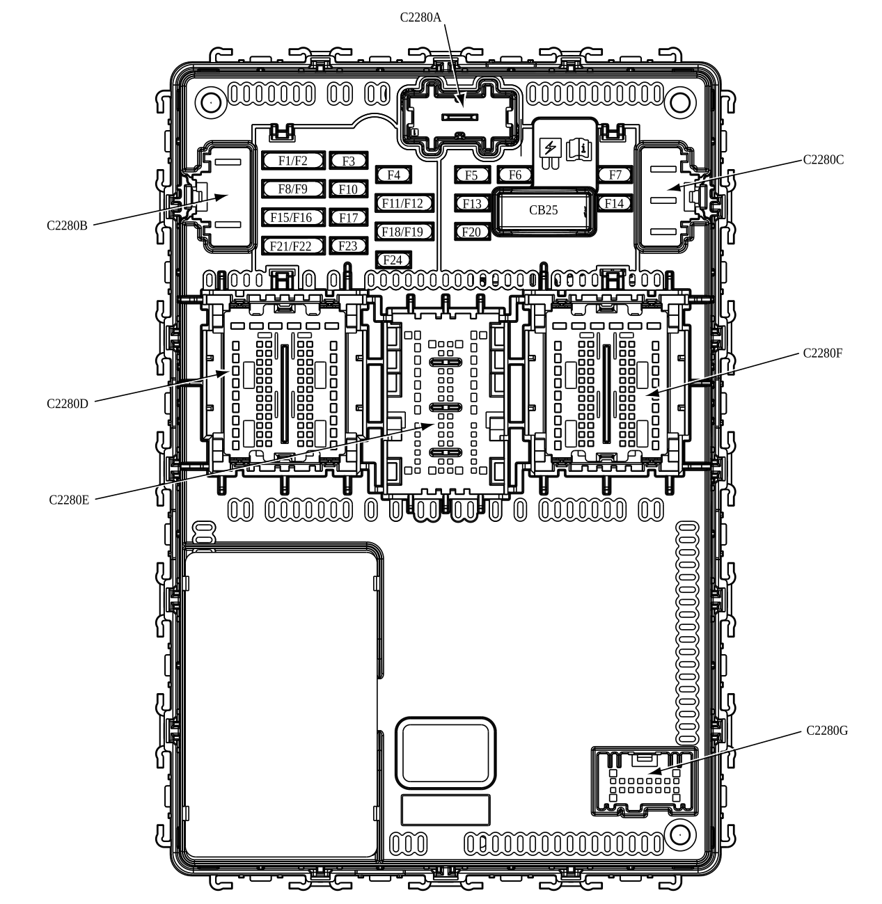 Schematic view of a Ford Fiesta BCM connector.
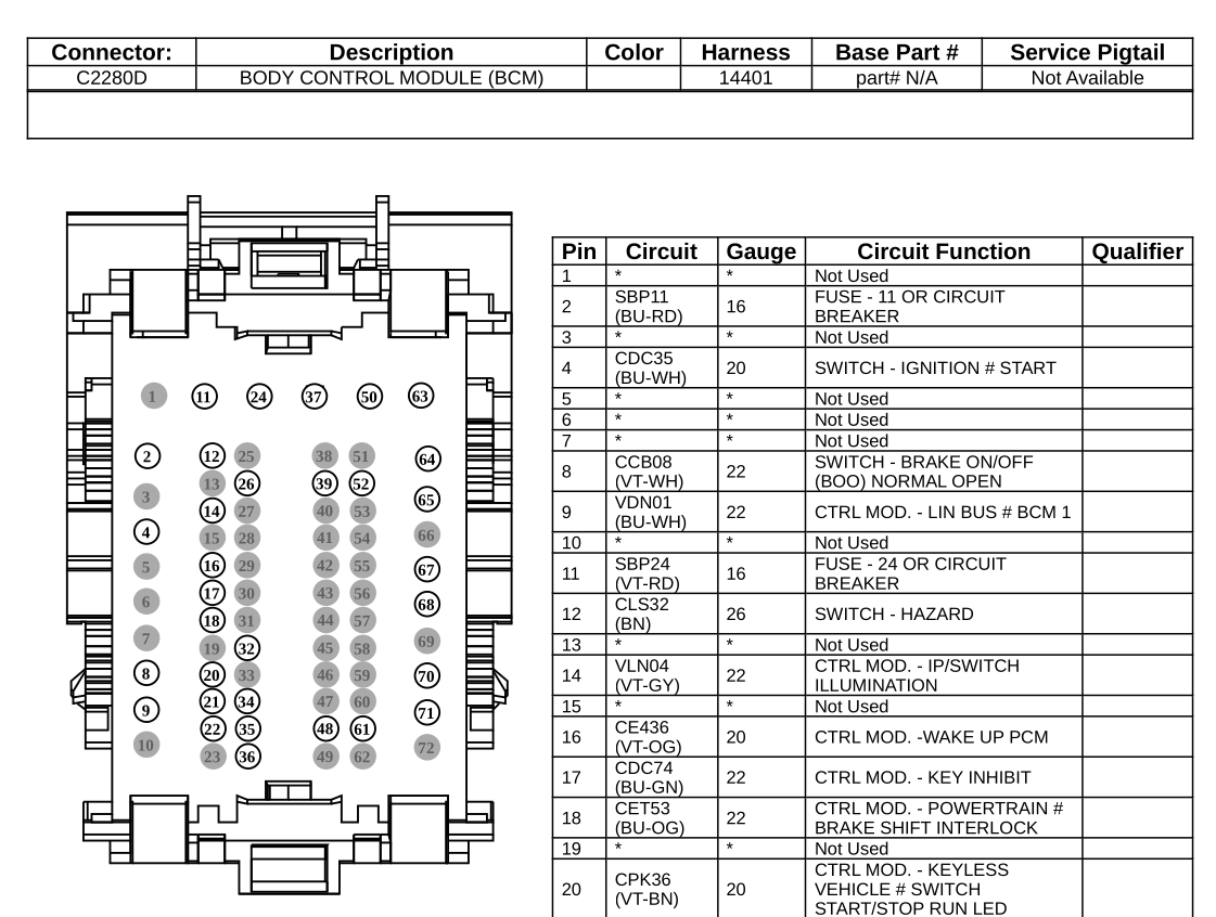 Pinout for the same Ford Fiesta BCM connector.
Component Location
When trying to find a specific component in a car, it helps to have a diagram that shows where it is located. This comes in handy when looking for a specific connector or ECU. Sometimes these diagrams are also available as a photo of the actual component.
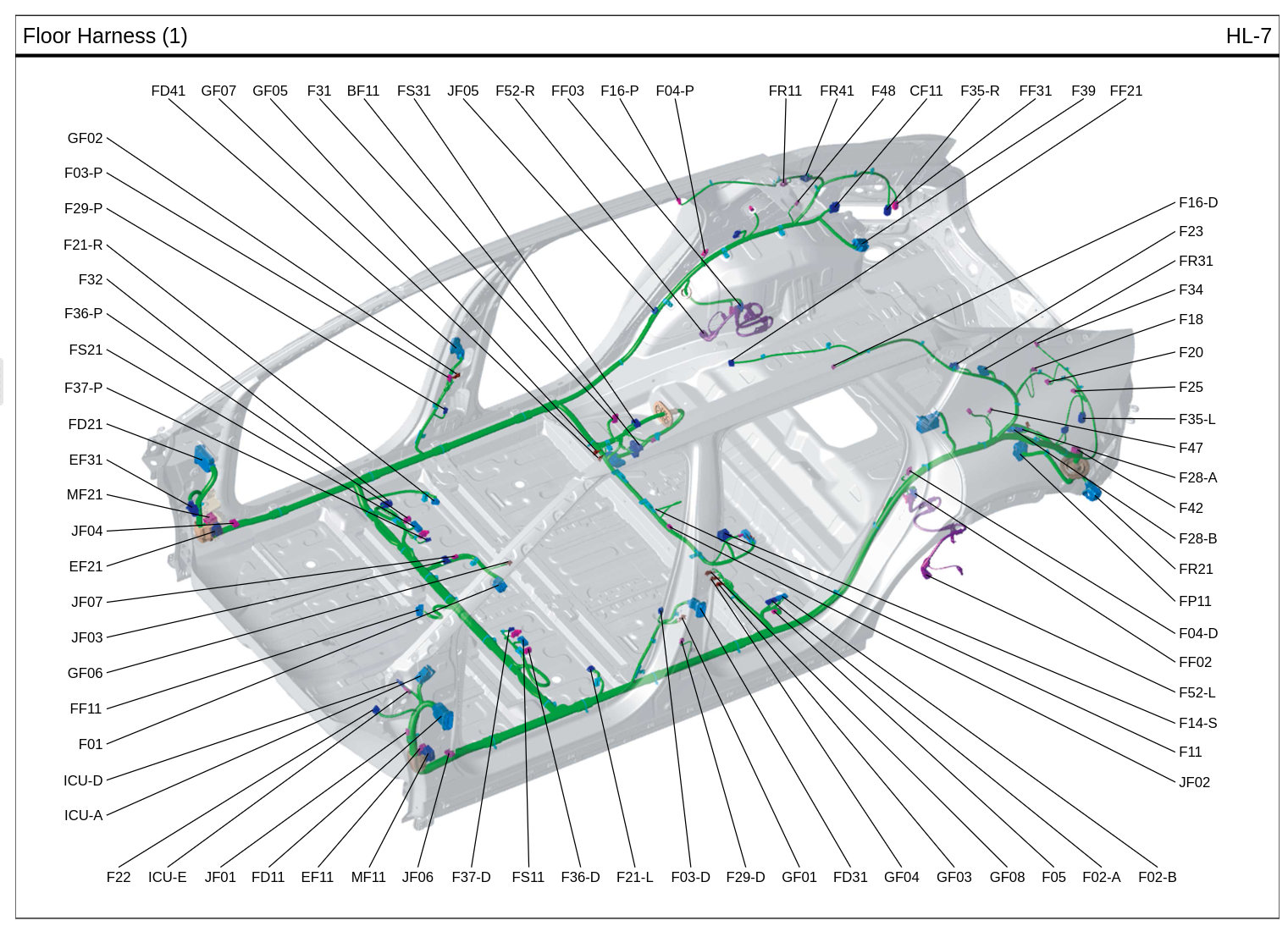 Schematic view showing the location of the JF01 connector on a Kia EV6.
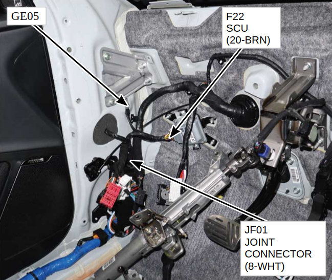 Photo of the JF01 connector on a Kia EV6.