Controller Area Network (CAN)
The CAN bus, also known as ISO 11898 [1], is a communication protocol widely used in modern vehicles to connect the various electronic control units (ECUs). Originally developed by Bosch in the 1980s and adopted as an ISO standard in 1993, CAN has become a fundamental part of automotive networks thanks to its reliability, scalability, and efficiency.
The 1991 Mercedes-Benz W140 S-Class was the first use of CAN bus in passenger cars, and was used to connect the ECUs related to engine management. This use quickly increased, and soon after, cars were equipped with multiple CAN buses to handle body electronics as well.
Around 2011, development of a CAN variant with higher throughput was started. In 2016, CAN FD was standardized, which supports more data per packet with faster data rates.
History
- 1986: CAN was developed by Bosch.
- 1991: Bosch published the CAN 2.0 specification.
- 1993: CAN was standardized as ISO 11898 [1].
- 2012: Bosch published the CAN FD 1.0 specification.
- 2015: CAN FD was standardized as ISO 11898-1:2015 [2].
- 2018: CAN XL Special Interest Group was formed.
Physical Layer
A CAN bus consists of two (twisted) wires, CAN-H and CAN-L, with a characteristic impedance of 120 Ω. It supports a maximum data rate of 1 Mbit/s over a maximum length of 40 m. Two or more nodes can be connected to the same physical bus, and any of them can initiate transmission at any time.
The signal is carried as a differential signal to improve resistance to external noise. The signal is encoded by driving a "dominant" state (logical 0), or leaving the bus idle for a "recessive" state (logical 1). By leaving the bus idle when transmitting a logical 1 and monitoring the bus during a transmission, it's possible to detect other nodes trying to send a message at the same time. This is used during the arbitration step to give messages with a lower identifier priority over messages with a higher identifier.
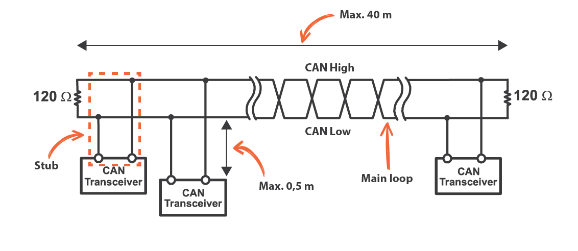 Three CAN Bus nodes connected using twisted pair wires and 120 Ω termination resistors at each end.
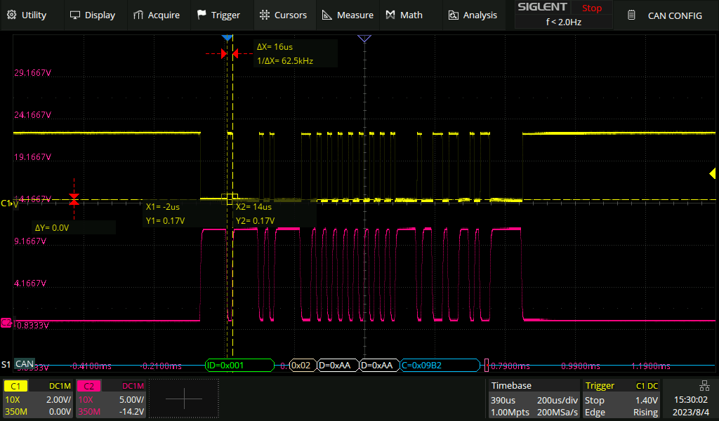
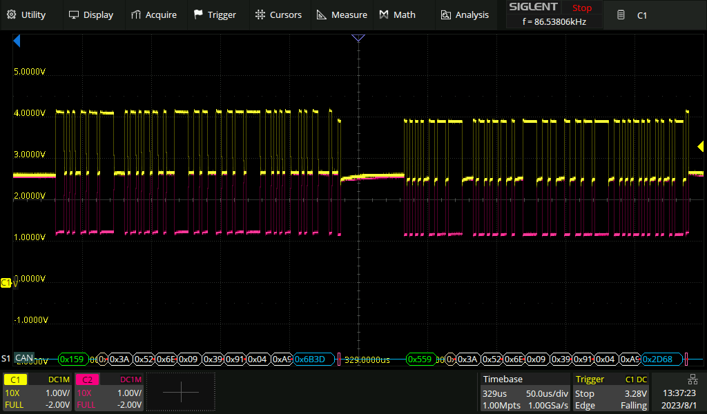 Two CAN frames on an oscilloscope. CAN High and CAN Low are shown in yellow and purple respectively.
CAN Frame
A CAN frame consists of a number of fields:
- SOF (Start Of Frame): Every CAN frame starts with a dominant bit to indicate the SOF.
- Arbitration ID: An 11-bit or 29-bit identifier. This is commonly used to identify the specific payload and/or the ECU that is sending the message. When multiple ECUs are trying to send a message at the same time, the message with the lowest arbitration ID gets priority. Hence the term arbitration ID. The 11-bit arbitration ID is followed by the IDE bit, which indicates whether the arbitration ID is 11-bit or 29-bit. If this bit is set to 1, the arbitration ID is 29-bit, and the next 18 bits are used as the rest of the arbitration ID. A CAN message with an 11-bit identifier is also known as a standard or CAN 2.0A frame, and a message with a 29-bit identifier is known as the CAN 2.0B or extended frame format. Sometimes the arbitration ID is also referred to as the address.
- RTR (Remote Transmission Request): It is possible for a controller to send out an RTR frame. The length field will be set to indicate the amount of data that is requested, but the frame itself does not contain any data. This is useful for requesting data from a different ECU. In vehicles this is usually not used during normal communication, but might be used for wake-up.
- Reserved bits: One or two (in case of extended frame) reserved bits, r0 and r1. Must be sent as dominant, but accepted as both recessive and dominant. This is used to allow for future extensions to the protocol, without breaking backwards compatibility.
- DLC (Data Length Code): A 4-bit field to indicate the number of data bytes (0 to 8).
- Data Field: Data to be transmitted. Length indicated by the DLC field.
- CRC: A 15-bit CRC calculated over the arbitration ID, RTR, DLC, and data field. The CRC is followed by 1 recessive bit for the CRC delimiter.
- ACK: The acknowledge part of the message consists of a recessive bit called the ACK slot, followed by 1 recessive bit of ACK delimiter. During the ACK slot all receivers send a dominant bit to acknowledge if the message was received correctly. If no receiver sends a dominant bit, the transmitter knows the message was not received correctly, and will retransmit the message. The sender cannot know if all nodes received the message correctly, only that at least one node did.
- EOF (End of Frame): 7 recessive bits that indicate the end of the message.
CAN 2.0A (11-bit Standard) Frame
| Field | Mnemonic | Value | Description |
|---|---|---|---|
| Start of Frame | SOF | 0 | A single dominant bit signaling the start of a frame. |
| Arbitration ID | ID | 0x123 | 11-bit identifier. Lower IDs win arbitration. |
| Remote Transmission Req. | RTR | 0 | Dominant — this is a data frame. |
| Identifier Extension | IDE | 0 | Dominant (0) — selects the 11-bit standard frame format. |
| Reserved | r0 | 0 | Reserved bit. Sent dominant; accepted as either polarity. |
| Data Length Code | DLC | 1 | 4-bit field encoding the number of data bytes (0–8 for classic CAN). |
| Data | DATA | DE | 1 byte of payload, transmitted MSB-first. |
| CRC | CRC | 0x7E45 | 15-bit CRC computed over SOF, arbitration, control and data fields. Stuff bits are excluded from the CRC computation. |
| CRC Delimiter | CRC-DEL | 1 | Single recessive bit between CRC and ACK. |
| ACK Slot | ACK | 0 | Transmitted recessive (1); receivers overwrite with dominant (0) to acknowledge a correctly received frame. |
| ACK Delimiter | ACK-DEL | 1 | Single recessive bit closing the ACK field. |
| End of Frame | EOF | 111 1111 | 7 recessive bits marking the end of the frame. |
Bit Timing
Each bit of a CAN frame is also divided into multiple parts. This is done to help with synchronization between different nodes.
Segments
Every bit of a CAN frame is divided into multiple segments. Each segment is made up of an integer number of Time Quanta (TQ).
- Synchronization Segment: Meant for timing synchronization between the different nodes. Bit edges are expected to occur within this segment. This segment is always 1 TQ long.
- Propagation Segment: Used to compensate for the delay between the nodes. This segment is between 1 and 8 TQ long, and is supposed to be twice the total propagation time on the bus. This is necessary in case more than one node is transmitting at the same time (during arbitration or acknowledgement).
- Phase Segment 1: Lies before the sample point, and can be lengthened to resynchronize. Between 1 and 8 TQ long.
- Phase Segment 2: Lies after the sample point, and can be shortened to resynchronize. Between 2 and 8 TQ long.
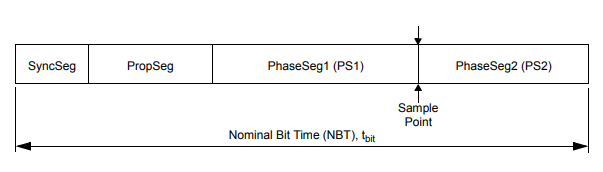 CAN Bit Time Segments
Synchronization
All nodes should be synchronized to within 1 TQ of each other, even though their internal clocks might run at slightly different frequencies. This is done by monitoring the bus during the synchronization segment. There are two types of synchronization, hard synchronization and re-synchronization. Hard synchronization happens at the beginning of a CAN frame, where every node synchronizes to the edge of the SOF bit.
Re-synchronization is a continuous process that happens when an edge from recessive to dominant occurs outside of the Synchronization Segment. If an edge is detected after the Synchronization Segment, Phase Segment 1 is lengthened by the amount of time the edge was early. If an edge is detected before the Synchronization Segment, Phase Segment 2 is shortened by the amount of time the edge was late, effectively starting the Synchronization Segment immediately.
Bit Stuffing
Each CAN controller on the network uses the edges in the signal to synchronize its clock. If a signal is idle for too long, the clocks can drift too far apart, and the receiver will not be able to correctly decode the message. To prevent this, the transmitter will insert a stuff bit after 5 consecutive bits of the same value. The polarity of the stuff bit will be opposite to the last 5 bits. The receiver will remove the stuff bit, and the original message will be recovered.
Bit stuffing is the reason why 0x55 (0b01010101), 0xaa (0b10101010), or 0xcc (0b11001100) are chosen as a common padding pattern over 0x00. The alternating pattern of ones and zeroes ensures no padding bits are inserted and the message length is not unnecessarily increased.
CAN Bus Errors
Each node on the CAN bus monitors the bus for certain error conditions. If an error is detected, an Error Frame is transmitted. An active Error Flag is a sequence of 6 dominant bits. Since this sequence of 6 bits violates the bit stuffing rule, any receivers that didn't already detect an error for the current frame will now also detect it and error out (and transmit a subsequent error frame). This makes sure that any erroneous messages are destroyed.
Alternatively, a passive Error Flag, consisting of 6 recessive bits, might be transmitted. This is like an active error flag where the node will stop transmitting any new data. However, it will not destroy messages on the bus sent by other nodes. This is useful if the affected node might be the source of the errors.
Since nodes might detect the error at different times, it's possible for multiple error flags to overlap. The total length of the error frame is therefore between 6 and 12 bits.
Types of Errors
There are five types of errors:
- Bit Error: The transmitting node will monitor the bus to ensure that the bit that it transmitted is the same as the bit that is received. If the bits don't match, a bit error is detected. Bit Errors during the arbitration phase or ACK slot are ignored.
- Bit Stuffing Error: Due to the bit stuffing process more than 5 consecutive bits of the same value should never be transmitted. If this happens anyway, a bit stuffing error is detected.
- Form Error: Some parts of the CAN frame are always dominant (SOF) or recessive (CRC delimiter, ACK slot, EOF). If the receiver detects an invalid value for these bits, a form error is detected.
- ACK Error: Raised by the transmitting node when no other nodes on the bus acknowledge a message.
- CRC Error: Raised by the receiving nodes if the CRC of the message does not match the CRC that was calculated over the received message by the receiving node.
Error States
To prevent malfunctioning nodes from blocking the entire bus with error frames, each node has three possible states:
- Error Active: The node is operating normally, and can send error frames whenever an error is detected.
- Error Passive: The node is operating normally, but will not send error frames. Whenever it detects an error it will send a passive Error Flag. After detecting an error it will also wait a bit before sending any new messages to allow other nodes on the bus to initiate a message.
- Bus Off: The node has disconnected itself from the bus at the protocol level. It will not send any messages or respond (ACK or Error) to any messages until it is recovered.
Error Counters
Every node keeps track of the number of errors that are detected. There are two counters, the TEC (Transmit Error Counter) and REC (Receive Error Counter). Every node starts in the Error Active state. When the TEC or REC exceeds 127, it transitions into the Error Passive state. Finally, when the TEC exceeds 255, it transitions into the Bus Off state.
Generally, the TEC is increased by 8 every time a node sends an Error Flag (both passive and active) while transmitting a message, and the REC is increased by 8 when sending an Error Flag on receiving a message. The TEC and REC are reduced by 1 on successfully transmitting or receiving a message, including receiving a valid ACK. The exact rules are a bit more complicated and there are some exceptions; refer to section 12.1.4.2 of the ISO 11898-1:2015 standard [2] for more details.
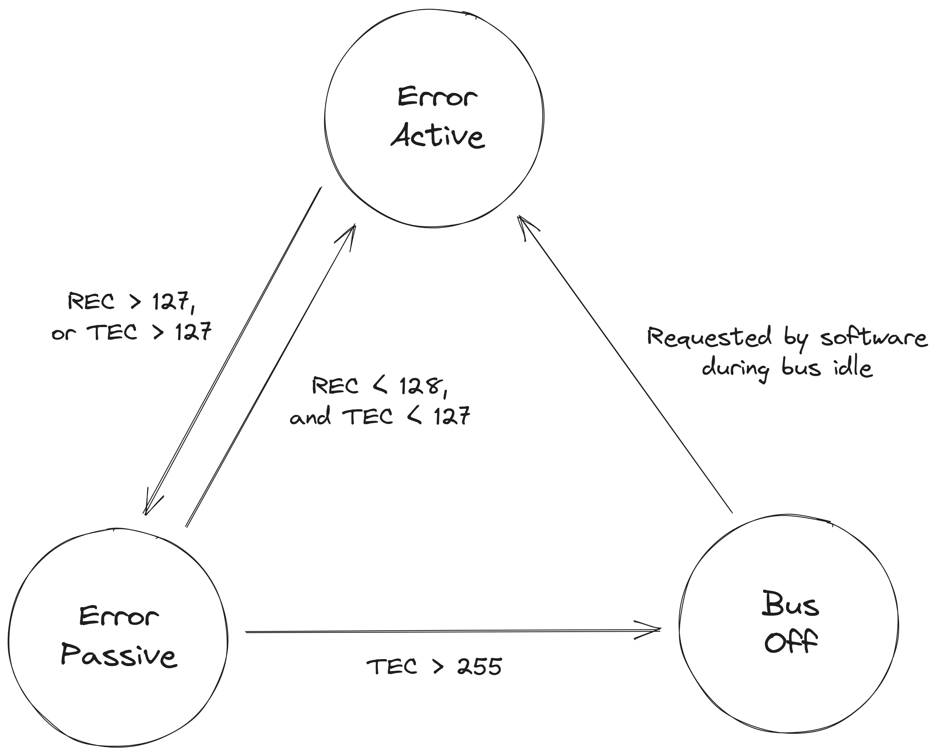 CAN Node Error States
Overload Frame
An Overload Frame is similar to an Error Frame, except that it's sent during the inter-frame spacing. It was meant as a way to indicate to other nodes on the bus that one of the receiving nodes is busy processing the data, and that they should wait before sending any new messages. An Overload Frame is repeated by all the other nodes like an Error Frame, however, no error counters are increased. Overload Frames are not used in practice anymore since microcontrollers have gotten a lot faster.
CAN FD
CAN FD is an extension to the original CAN bus protocol. It was developed in 2011 by Bosch, and standardized in 2015 in ISO 11898-1:2015 [2]. It's backwards compatible with the original CAN protocol, and allows for up to 64 bytes per packet with faster data rates up to 5 Mbit/s (or up to 8 Mbit/s for new transceivers that support CAN SIC).
Data Field
To keep backwards compatibility between CAN FD and CAN, the arbitration phase is sent at the original CAN data rate. CAN FD replaces the classic CAN r0 bit with the FDF bit. If FDF is recessive, the frame is a CAN FD frame and some additional fields are sent that are not part of the regular CAN standard.
- FDF (FD Format): Replaces r0 in classic CAN. If this bit is recessive, the frame is a CAN FD frame.
- Reserved Bit: A new reserved bit, in case a new extension is needed in the future.
- BRS (Bit Rate Switch): Indicates if the data portion of the message will be sent at a higher bit-rate (recessive) or at the same bit-rate as the header (dominant).
- ESI (Error State Indicator): Indicates if the sender is in error passive mode.
- DLC: Still 4 bits long. 0 to 8 still means 0 to 8 bytes of data, but 9 to 15 are now mapped to 12, 16, 20, 24, 32, 48 and 64 bytes of data.
- SBC (Stuff Bit Count): Placed before the CRC and indicates the number of stuff bits.
- CRC: 17 bits long for messages up to 16 bytes, and 21 bits for messages up to 64 bytes.
Backwards Compatibility
A CAN FD node can be connected to the same bus as regular CAN nodes. The CAN FD node will be able to receive messages from the regular CAN nodes as well as CAN FD nodes. However, when a CAN FD message is sent, regular CAN nodes will flag it as an error. In practice, this means mixed CAN/CAN FD buses only work if the CAN FD nodes send classic CAN frames while regular CAN nodes are present on the bus.
Non-ISO CAN FD
The first specification of CAN FD was published by Bosch in 2012, and was proposed for standardization. During the standardization process, several theoretical weaknesses were found in the error detection mechanisms. This required the introduction of extra safeguards such as the Stuff Bit Count. These changes were not backwards compatible with the original CAN FD specification, and therefore a new specification was published in 2015 as ISO 11898-1:2015 [2].
Non-ISO CAN FD is supported as a special mode by most CAN controllers, and is still used in practice in some applications.
Other Variants
CAN XL
CAN XL is the third generation of CAN networks. It is meant to fill the gap between CAN FD and Automotive Ethernet. It supports data rates up to 20 Mbit/s and up to 2048 bytes per frame. CAN XL controller IP is available, such as Bosch X_CAN and Arasan CAN-XL, and early MCU/SoC integrations exist, such as Infineon AURIX TC4x variants with a Q feature package. Standalone USB adapters are also starting to appear, such as PEAK-System's PCAN-USB XL.
Low-Speed / Fault-Tolerant CAN
LS-CAN or FT-CAN operates at lower speeds up to 125 kbit/s, and is mostly used for convenience features. It uses two wires, where each wire has its own termination resistor. In case of a failure or short circuit in one of the wires, the transceiver can switch to a single-wire mode.
Single Wire CAN (SW-CAN)
SW-CAN is a single-wire variant of CAN that operates at 33.3 kbit/s (or 83.3 kbit/s in high-speed mode) and is standardized in SAE J2411 [3].
It's used for communication in GMLAN. It was also used in Tesla vehicles for communication between the car and the EVSE before they switched to PLC to follow DIN 70121 [4] / ISO 15118 [5].
 SW-CAN frame on an oscilloscope. The transceiver TX input is shown in yellow and the SW-CAN bus in purple.
Time Triggered CAN (TT-CAN)
Due to how arbitration works in a CAN network, it can be impossible to predict how long it will take to send a message successfully. This can be an issue for safety-critical systems that need real-time communication, e.g. drive-by-wire systems. As a solution, TT-CAN was developed and standardized in ISO 11898-4 [6].
In TT-CAN, the communication is divided into cycles. Each cycle begins with a reference message from a designated time-reference node and is divided into a number of time slots, where each node is assigned a time slot. This way, it's possible to predict how long it will take to send a message, and it's possible to guarantee a maximum latency. At the end of each cycle there is a window for spontaneous messages, which can be used for messages that are not time-critical and follow regular CAN arbitration. Retransmissions are not allowed in TT-CAN (both for spontaneous and time-triggered messages).
Practical Attacks
Man-in-the-Middle Attack (MITM)
Since CAN has no real-time requirements on the communication, implementing a MITM attack is trivial. The attacker can simply receive the traffic on the bus, and retransmit the messages to the intended receiver. This way the attacker can modify the messages before they reach the receiver, or even block messages from being sent.
This introduces a delay comparable to the time it takes to receive the message. However, since this delay might also be caused by a retransmission, the receiver cannot know if the delay is caused by a MITM attack or not.
Denial of Service (DoS)
By sending a large number of messages with a certain arbitration ID, it's possible to block other messages from being sent with a higher arbitration ID (lower priority). This can be used to prevent safety-critical messages from being sent, which can lead to a malfunction of the system or (temporary) disabling of an Intrusion Detection System (IDS).
Overload Attack
Another way to perform a DoS attack is by sending overload frames. This will cause all of the nodes on the bus to stop sending messages, without increasing the error counters. The feature of overload frames is part of the CAN spec, and might be implemented in the CAN controller. Since no error counters are increased, the application might not notice transmissions are blocked.
CAN Priority Inversion
Priority inversion is similar to Denial of Service, but arises from a misconfiguration of the CAN controller in an ECU. Usually there is a queue of messages that need to be sent out on the CAN bus. If the programmer is not careful, this queue will be implemented in a FIFO fashion.
The problem with this approach is that if a message with a high arbitration ID (low priority) is placed in the queue, it can block messages with a lower arbitration ID (high priority) from being sent out. If the bus load is high, this can lead to a high-priority message being delayed for a long time, which can lead to a malfunction of the system.
The solution is to make sure that the queue is implemented as a priority queue, so that messages with a higher priority are always sent out first. If a higher-priority message is put in the queue, it's also important that any lower-priority messages that are currently being sent out by the controller are cancelled, and the higher-priority message is sent out immediately.
Janus Attack
The Janus Attack is described by Tindell (2021) [7] and later adapted for CAN FD by Ziv (2022) [8]. The Janus attack is named after a Roman god usually depicted with two faces. The Janus attack consists of a carefully crafted message that is received as having a different payload by two different nodes by abusing the difference in sampling points between the two different receivers.
DLC > 8 bytes
Regular CAN packets can only hold up to 8 bytes; however, the DLC is 4 bits in size, so it can hold values up to 15. If the DLC is not checked properly on the receiving side, and used as an argument for a memcpy or similar function, it's possible to write more data than the buffer can hold. This can lead to a buffer overflow, and potentially code execution.
Many hardware abstraction layers provided by vendors expose the DLC field to the user without proper checks.
Counters
If there is space in the payload of a CAN message, usually a counter is included. This is useful in an ECU's firmware to detect if messages are still being updated and if no messages have been dropped.
Checksums
It's also common for safety-critical CAN messages to include a 4- or 8-bit checksum. For CAN FD this can also be a 16-bit checksum. Even though CAN messages are already protected by a CRC when being transmitted on the bus, this doesn't account for any errors that occur when the message is copied around in an ECU's RAM.
When actively sending messages on the CAN bus it might be necessary to compute the checksum. There are a few common checksum algorithms that will be discussed below. However, even though a message contains a checksum, it's often not enforced by non-critical ECUs such as the instrument cluster.
XOR
A simple checksum algorithm is to XOR all the bytes in the message. It is quick to compute, and detects all single-bit errors and some multi-bit errors, but many multi-bit error patterns can cancel out.
Sum of Bytes
Another simple checksum algorithm is to add all the bytes in the message together and truncate to 8 or 4 bits. It too is quick to compute, and detects all single-bit errors and some multi-bit errors, but many multi-bit error patterns can produce the same sum.
Variants of this algorithm also add the length of the message and/or the arbitration ID to the sum. Another variant is to subtract the summed value from 256 (8-bit checksum) or 8/16 (4-bit checksum). Finally, it's also possible that the sum is not done for each byte, but done for each nibble separately.
AUTOSAR CRC
AUTOSAR specifies a few CRC variants such as CRC8, CRC8H2F, CRC16, CRC16ARC, and some 32- and 64-bit variants [9].
Specifically CRC8H2F is interesting as it's used by Volkswagen Group cars. They take the specified implementation, but XOR with a magic byte at the end of the computation. This magic byte is different for each arbitration ID, and sometimes also depends on the counter value.
XMODEM-CRC
The 16-bit XMODEM-CRC is used by Hyundai/Kia cars using their new CAN FD architecture. The arbitration ID is included in the computation of the CRC (after the message). Finally, the result is XORed with a magic value based on the length of the message.
Jeep & Chrysler
Jeep & Chrysler use a custom algorithm involving a bunch of shifts and XORs. Refer to the Remote Exploitation of an Unaltered Passenger Vehicle paper by Charlie Miller and Chris Valasek [10] for more details.