Ghidra Tutorial
Ghidra is the NSA's open-source software reverse engineering suite [1]. It is well suited to automotive work: it is free, scriptable in Python and Java, and its decompiler supports the cores commonly found in ECUs (PowerPC VLE, TriCore, RH850), which other tools either do not support or only support at significant cost. This chapter covers the practical steps of using it on a raw firmware image, from import through to a labelled UDS dispatcher.
The CodeBrowser
The CodeBrowser is the main analysis window. The relevant panes are:
- Listing: the disassembly with markup (labels, comments, references).
- Decompiler: the pseudo-C view of the function under the cursor.
- Symbol Tree: imports, exports, namespaces, and defined symbols.
- Data Type Manager: built-in and imported types, and user-defined structures.
- Memory Map: the section table, edited through this pane.
- Bookmarks: analysis warnings and user notes.
- Defined Strings: every string Ghidra recognised. Firmware images contain few strings, but those that exist (debug messages, AUTOSAR module names, version banners) are useful starting points for analysis.
- Function Graph: the control-flow view of the current function.
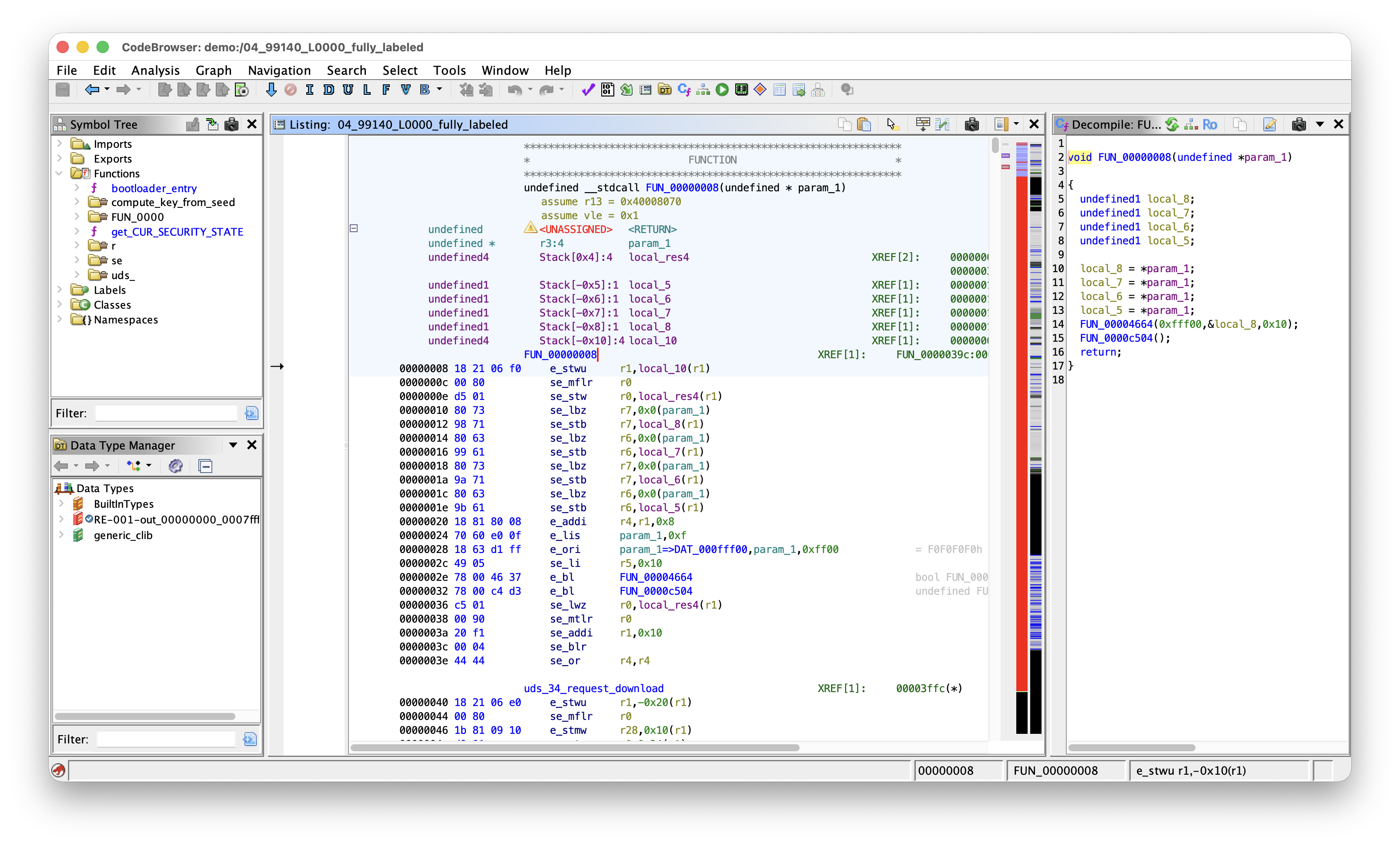 Ghidra CodeBrowser with Listing, Decompiler, Symbol Tree, Data Type Manager and Memory Map panes visible on an automotive firmware image.
SLEIGH and P-code
SLEIGH is the specification language Ghidra uses to describe a processor [2]. Each instruction is defined in two parts. A constructor matches a bit pattern and decodes it to a mnemonic and operands. A semantic block in {} emits p-code, the architecture-neutral intermediate representation that the rest of Ghidra (the decompiler, the data-flow analyser, scripts) operates on.
A simplified example of a SLEIGH entry:
:add Rd, Rs1, Rs2  is op=0b000000 & Rd & Rs1 & Rs2  {
    Rd = Rs1 + Rs2;
}
The decompiler operates only on p-code, with no per-architecture code. Any architecture with a SLEIGH specification therefore produces full decompiler output. PowerPC VLE, TriCore, and RH850 are usable in Ghidra for this reason, and adding a new automotive core requires only a new SLEIGH file.
Recognising Automotive Firmware Layout
An ECU image typically splits into a small bootloader (CBOOT) and a larger application (ASW).
The Entropy strip on the right of the Listing makes the split visible. Code and packed lookup tables sit around 6 bits per byte. Calibration constants and pointer tables are lower. Padding gaps drop to near zero. Compressed or signed blobs remain flat near 8. The typical pattern is a small dense band (CBOOT), a low gap, a much larger dense band (ASW), with occasional flat regions for tables and a tail of padding. This indicates where to place the loader sections before any disassembly.
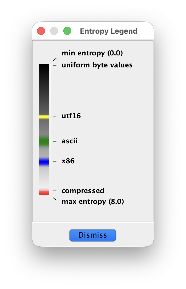 Ghidra entropy legend.
Loading a Firmware Image
For a raw memory dump, use File, Import with the format set to Raw Binary. The processor dropdown is the only field that has to be set carefully, and the correct variant matters:
- PowerPC: select
PowerPC:BE:32:e200for the Power Architecture e200 cores common in MPC55xx/57xx parts. Thedefaultvariant is plain Book-E and will not decode VLE. - TriCore:
tricore:LE:32:defaultcovers Infineon AURIX TC1.6.x. - RH850: shipped as a variant of
V850, typicallyV850:LE:32:defaultwith the RH850 extensions enabled.
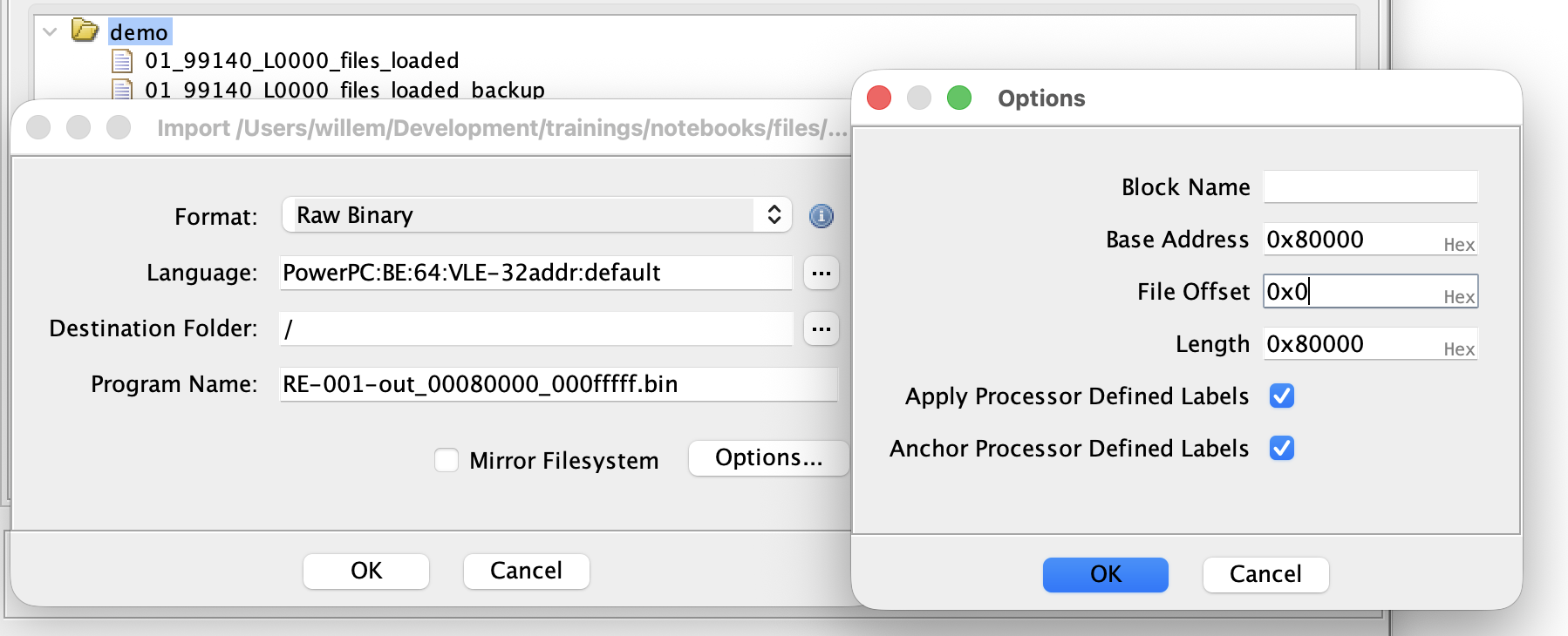 Import dialog loading a PowerPC VLE binary with a loading offset of 0x80000
After import, the entire image is loaded as a single block at the address given. Most automotive images require a finer split. Open Window, Memory Map and split the block so CBOOT and ASW are mapped at their real addresses. Keep in mind that TriCore PFLASH is mapped at both 0x8000_0000 and 0xA000_0000.
Setting Up the Memory Map
The Memory Map editor is also used to define RAM and peripheral regions. From the datasheet:
- A RAM block at the chip's SRAM base. Read/Write. Executable depending on context. Some applications copy part of the code to RAM for faster execution, this is especially common on TriCore.
- One or more MMIO blocks for the peripherals. Mark these Volatile. Without Volatile, the decompiler folds repeated reads of a status register to a single value and constant-propagates the result, so polling loops appear as infinite loops and the surrounding logic disappears from the output.
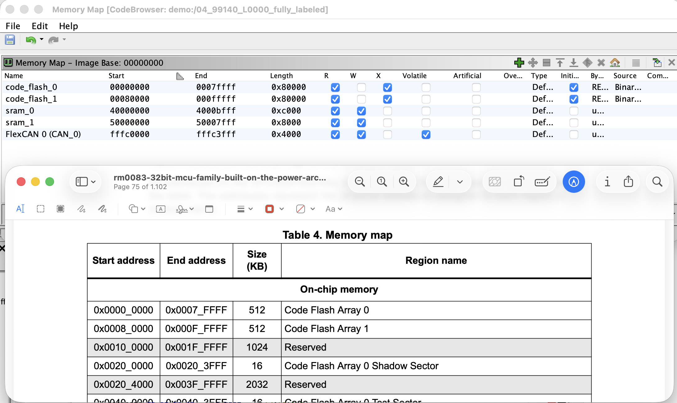 Memory Map editor populated with Flash sections, SRAM blocks, and a peripheral block marked Volatile.
Auto-Analysis Options
Ghidra runs a stack of analysers after import. Two of them produce false positives hindering further analysis, and should be enabled for running Analyze, Auto Analyze before the first run:
- Address Tables interprets aligned, pointer-shaped regions as jump or pointer tables and disassembles the targets. It runs early, before the code finder has identified real code, so an incorrect guess claims a data region as a table. This prevents later analysers from revisiting that region as code.
- Non-Returning Functions heuristically marks functions such as
panic,abortorexitas no-return. A single false positive truncates control flow at every call site and leaves unreachable code behind each call.
Two further options are worth reviewing: Decompiler Parameter ID is slow on large images and is better left for a second pass once the bulk of the labelling is done.
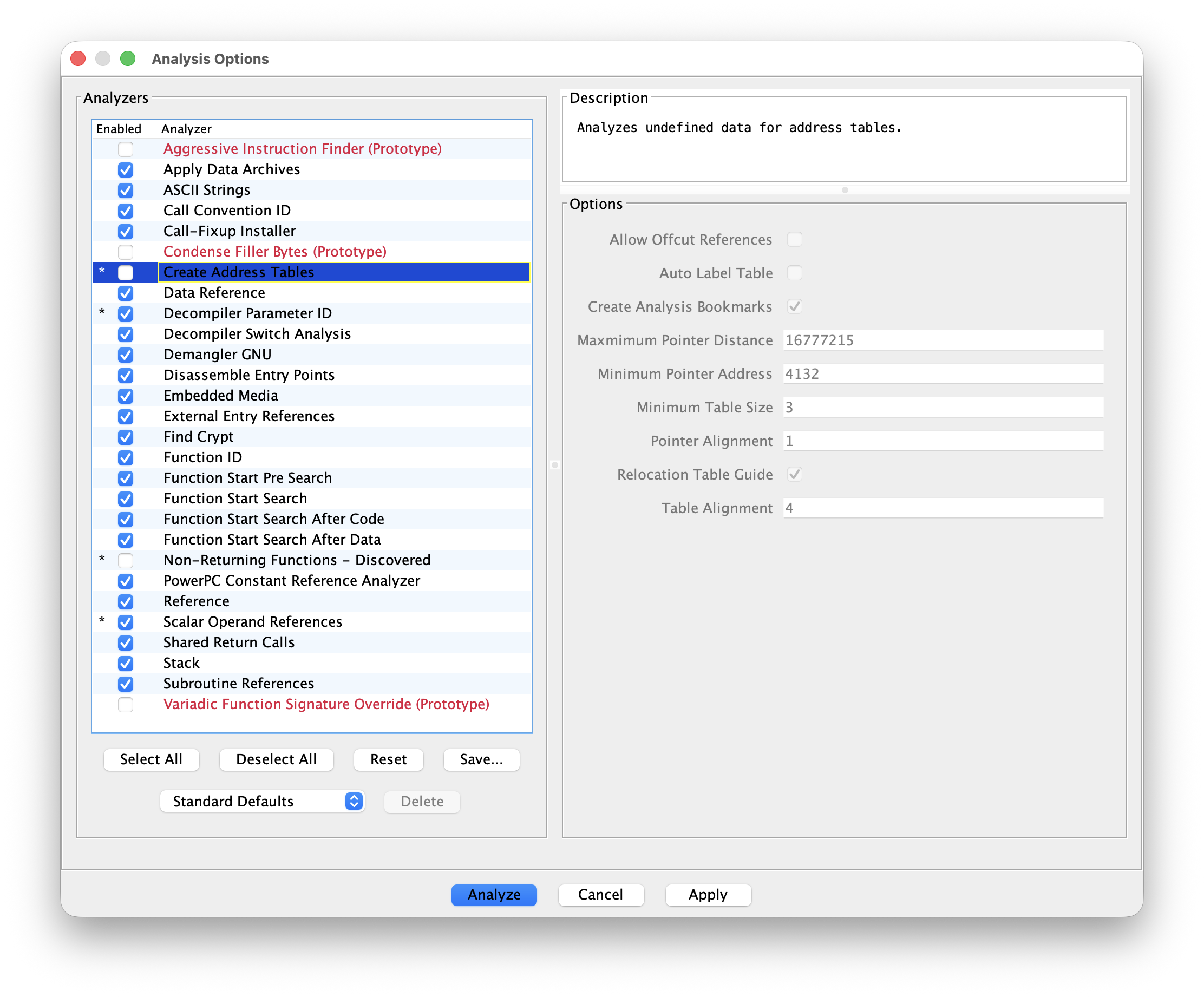 Analysis Options dialog with Address Tables and Non-Returning Functions unticked.
Finding the Boot Header
The boot header is the fixed-format structure the mask ROM reads first to decide how to start the chip. Each architecture defines its own:
- PowerPC (MPC55xx/57xx) uses a boot header near the start of the flash, with magic bytes, an entry point address and configuration words.
- TriCore AURIX uses a Boot Mode Header (BMH) at fixed addresses (typically 0x80000000, 0x80020000, and so on).
- RH850 stores option bytes and the reset vector in dedicated regions defined by the device's datasheet.
Locate the header, confirm that the entry point references plausible startup code (a stack pointer load, an unconditional branch to higher addresses), and label it. The rest of this chapter assumes the load address is correct, and the boot header is the structure that confirms it.
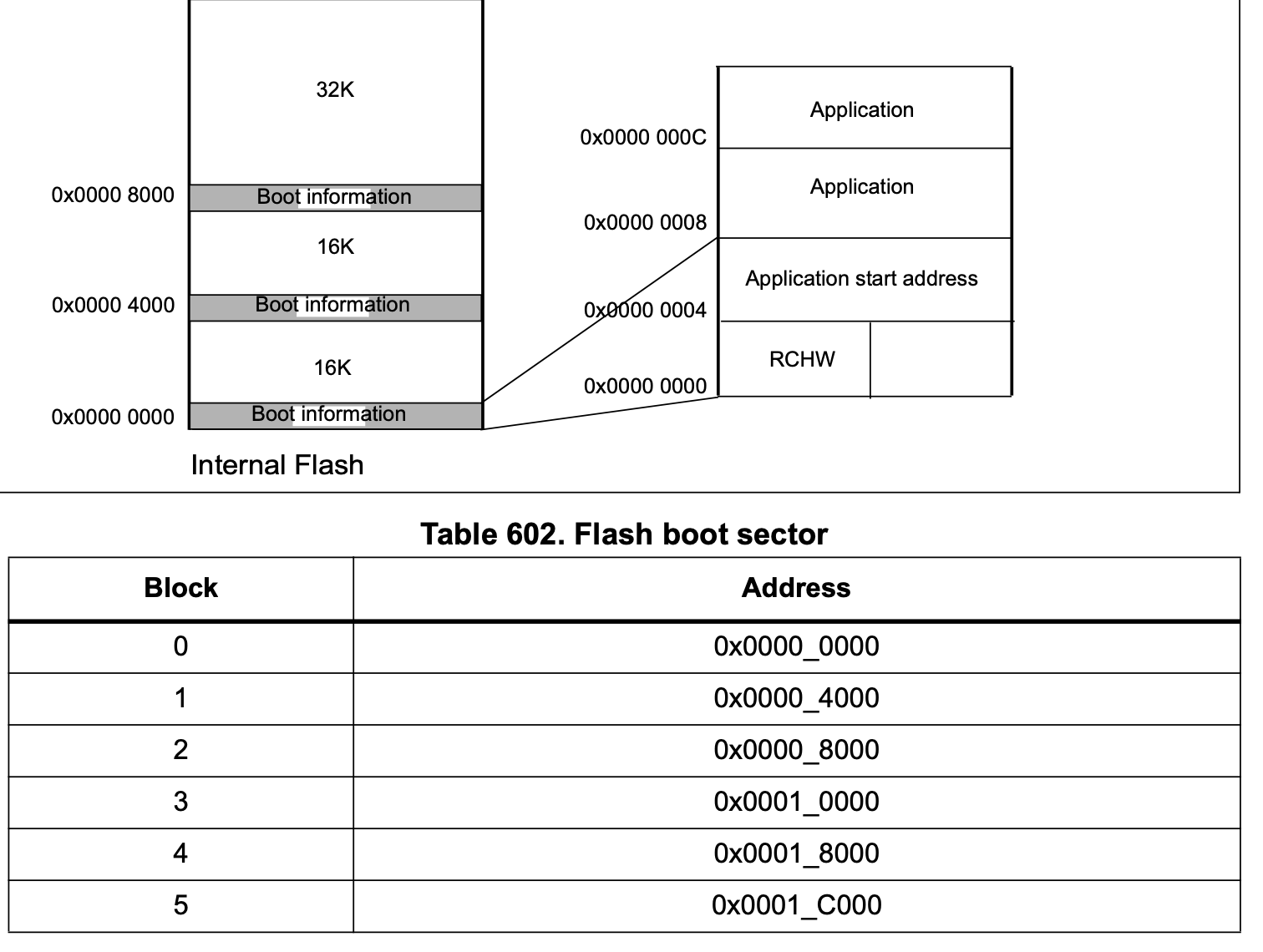 Datasheet excerpt showing the boot header layout for one of the supported architectures, with the magic word, entry point and configuration fields identified.
Disassembling Code
With the auto-analysis options adjusted, run Analyze. Review the result and identify regions that were skipped. Long runs of ?? (undefined bytes) between functions are typically code that the auto-analysis did not reach. Select the start address and press D.
On PowerPC VLE, the analyser disassembles in Book-E mode by default. The two encodings overlap sufficiently that Book-E will decode VLE bytes into syntactically valid but incorrect instructions. In automotive typically only VLE is used, so press F12 to disassemble the region in VLE.
The Entrypoint and Global Registers
Each of the architectures above reserves one or two registers as bases for the Small Data Area (SDA). The compiler emits global accesses as reg + offset16, avoiding a lis/ori-style pair on every load and store. The SDA bases are set once in the startup code and remain fixed for the lifetime of the program.
The decompiler has no knowledge of the SDA base values until they are configured. Until then, every global access decompiles as *(int *)(r13 + 0x1234) and produces no cross-references. Select all code where the found SDA values apply, typically bootloader or application code, though microcontrollers with multiple cores might use different register values per core. Use Right-click in Listing, Set Register Values to tell Ghidra about the correct register values. This will clean up the decompilation and calculate the correct X-refs on the next Auto Analysis pass.
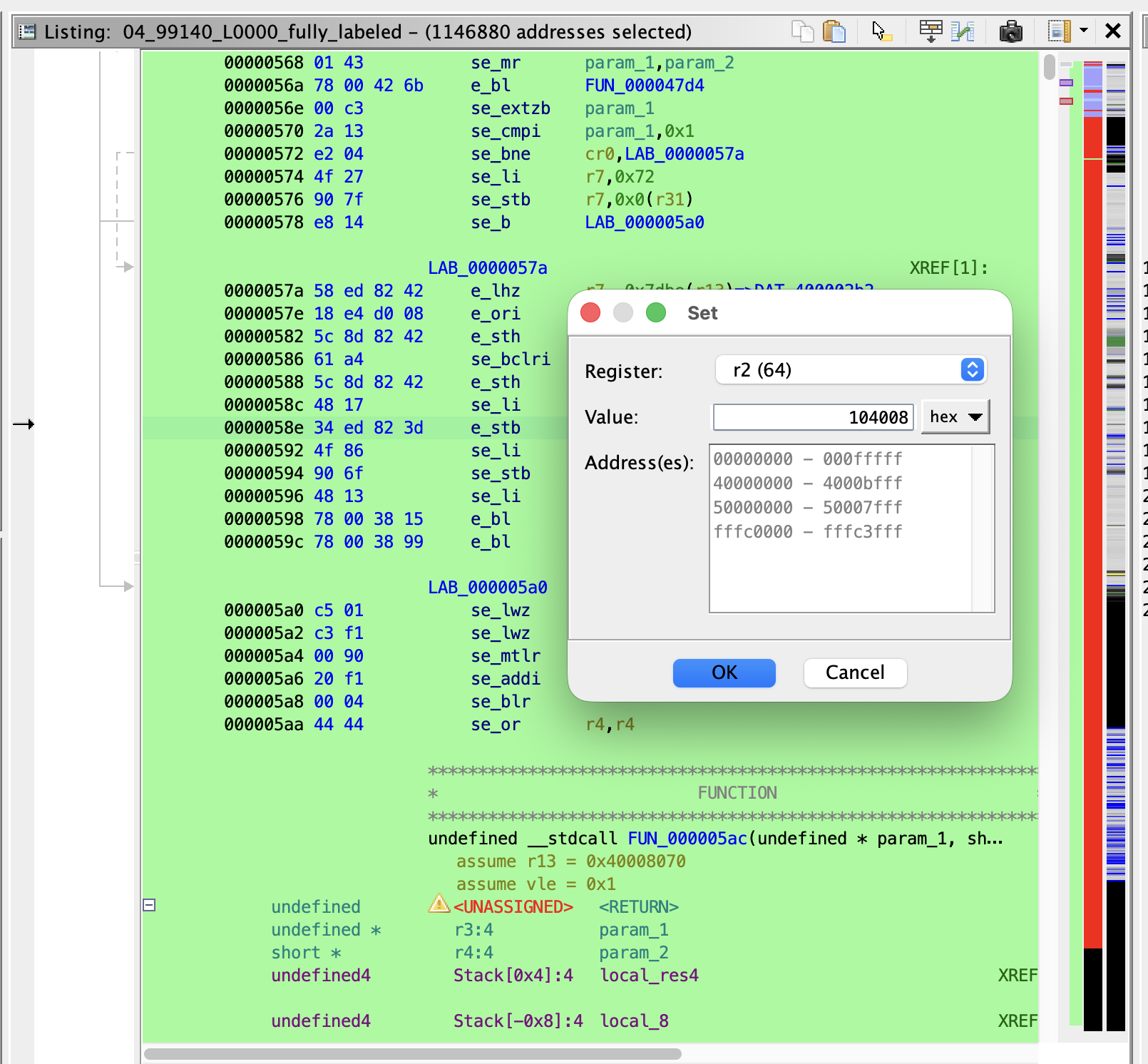 Edit Register Values dialog with r2 and r13 set to their SDA base addresses on a PPC VLE entry function.
The bases are loaded immediately after reset:
- PowerPC VLE:
r2is SDA2 (.sdata2/const),r13is SDA (.sdata). Startup typically loads them withe_lis r2, hi ; e_or2i r2, loand the same forr13.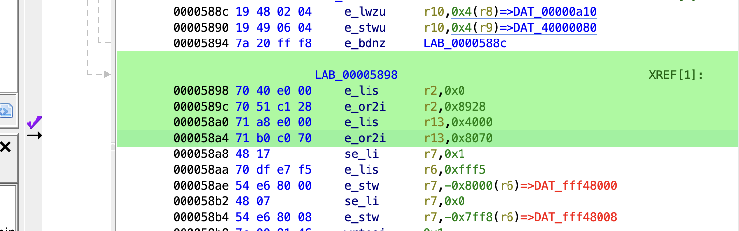 Typical PPC VLE startup code setting r2 and r13 to the SDA bases.
 - TriCore:
a0anda1cover the small data areas,a8anda9are reserved for the OS/application split. Startup usesmovh.a a0, hi ; lea a0, [a0]loand similar fora1.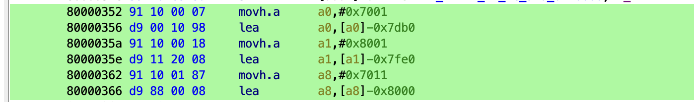 Typical TriCore startup code setting a0 and a1.
 - RH850:
r4isgp(globals),r5istp(thread/task pointer).r0is hard-wired to zero and requires no setup. Startup usesmovhi hi, r0, r4 ; movea lo, r4, r4to loadgp.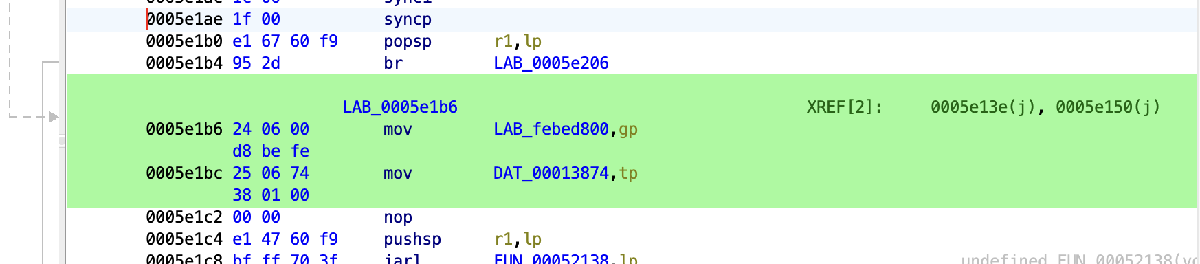 Typical RH850 startup code setting gp and tp.
Configure the registers once at the reset entry function. Edit Register Values can be set to propagate forward through called functions, which avoids repeating the setup on every callee.
Finding the UDS Handlers
A practical entry point on a stripped image is to search for constants that the firmware is required to contain. The negative response codes from the UDS chapter are suitable for this: every ECU that implements UDS must return them, the values are fixed by ISO 14229, and they appear as immediate constants in the handler code.
Useful constants for Search, For Scalars:
0x35invalidKey0x33securityAccessDenied0x12subFunctionNotSupported0x13incorrectMessageLengthOrInvalidFormat0x11serviceNotSupported0x22conditionsNotCorrect0x7Fnegative response marker, often written into the response buffer before transmit
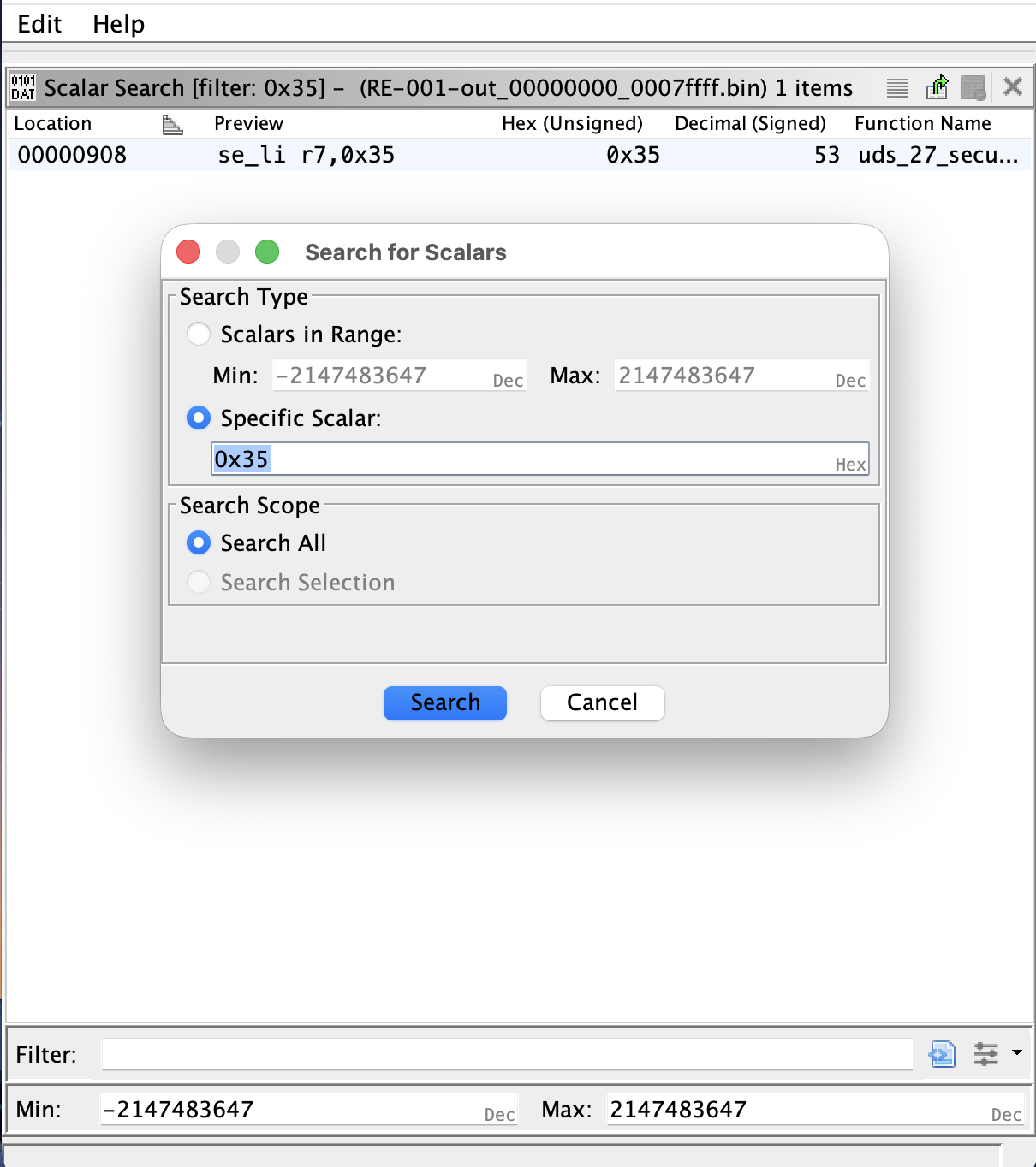 Search For Scalars dialog with 0x35 entered, and the results window showing several hits in the application region.
Select a value, run the search, and walk the xrefs back. An NRC literal sits in a specific service handler. Each service handler is reached from a dispatcher, which is either a switch on the SID or an indexed call through a table. The dispatcher is reached from the diagnostic message receive path. Two hops back from one NRC is generally sufficient to reach the top of the diagnostic stack, from which every service handler can be enumerated.
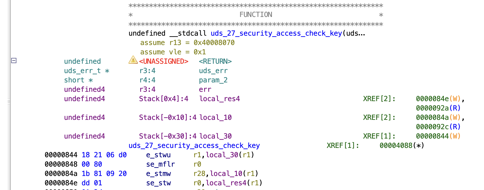 Xref chain from an NRC literal back through a per-service handler to the dispatcher table.
Typical Configuration Structures
Much of an ECU's behaviour is driven by static tables of structures: UDS dispatchers, CAN message descriptors, RTOS task lists. Defining the structure once in the Data Type Manager and applying it to the table base causes the Listing to label every field of every entry, which generally yields a full inventory of the relevant subsystem in a single pass.
UDS Handlers
The UDS handler table commonly contains fields like:
- SID (
u8) - minimum request length (
u8) - session mask (
u8oru16): the sessions in which the service is permitted - security mask (
u8): the required security levels - handler function pointer
- pointer to further configuration of sub-function handlers
Sometimes the table contains the SIDs directly, or those are stored separately.
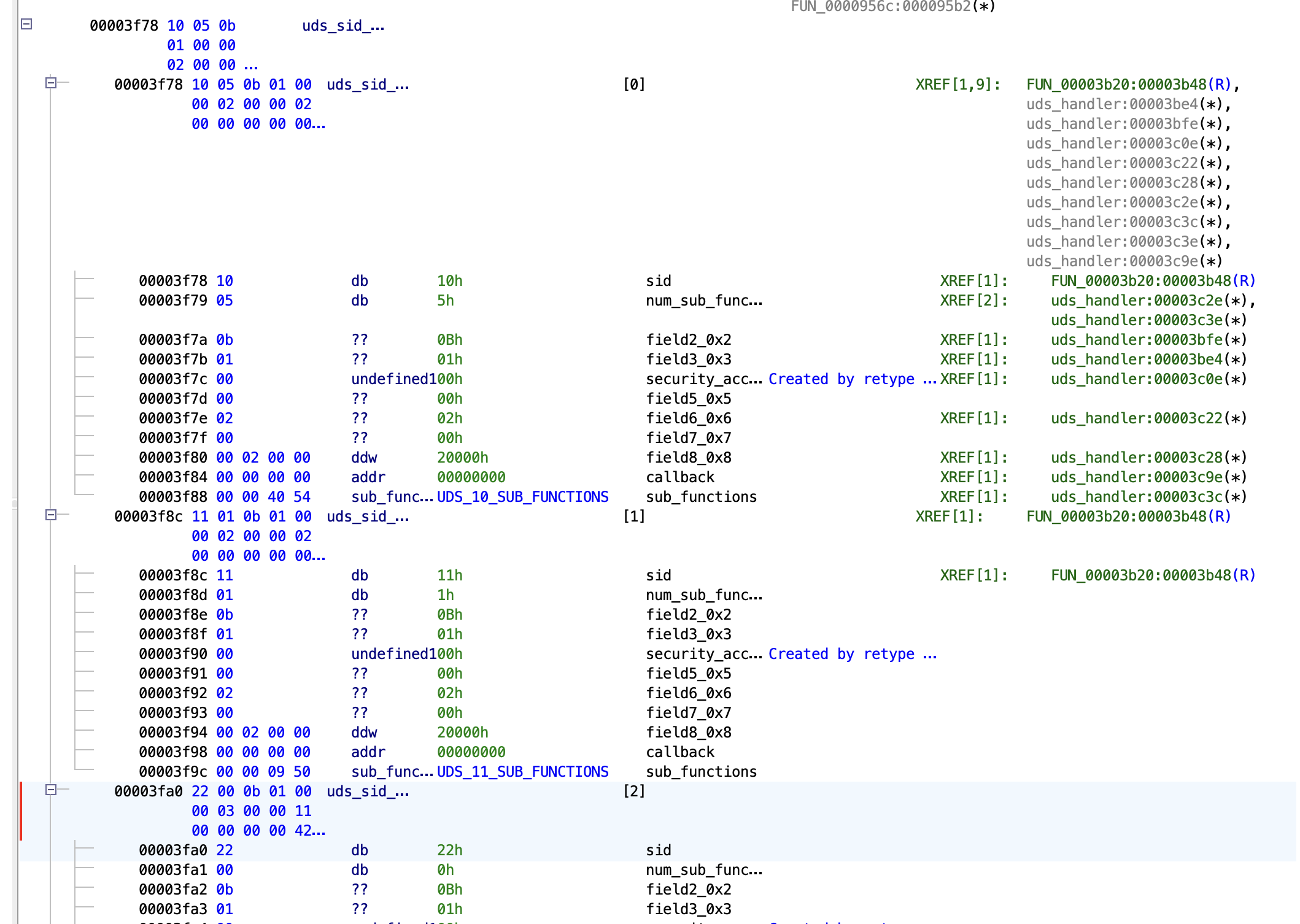 UDS handler table struct applied to the table base, with each entry's SID, masks and handler pointer labelled.
CAN Parsing
The CAN parsing table typically contains a list of signals. For each signal the bit layout inside a message is specified. Functions that pack or unpack CAN messages typically contain multiple calls to a generic packer/unpacker function with the signal IDs belonging to that message.
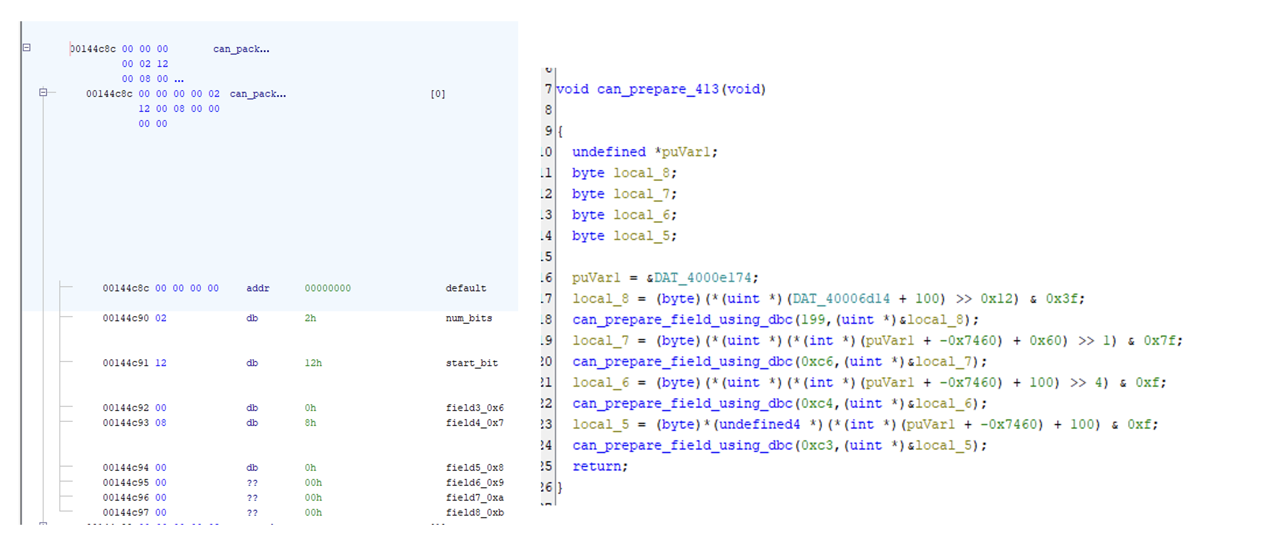 CAN parsing table defining the signals.
RTOS Threads
Automotive ECUs run an OSEK or AUTOSAR OS variant in which tasks are statically configured at build time. The task table is fixed in flash and commonly contains one or more of the following values per task:
- task ID or name pointer
- priority
- stack base pointer and stack size
- entry function pointer
Locating the task table gives the full set of periodic and event-driven entry points in the firmware. Each entry function is a useful starting point for understanding what the ECU does at runtime, and the priorities indicate which tasks the scheduler favours under load.
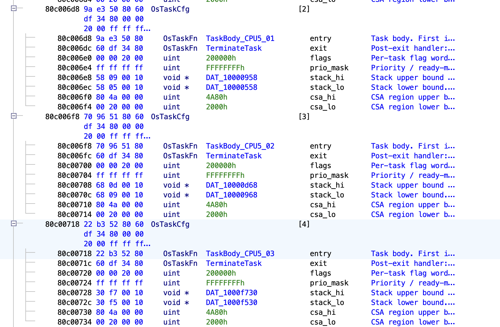 RTOS task table struct applied to the table base, with each task's priority, stack pointer and entry function labelled.
AUTOSAR
Most automotive firmware produced in the last decade conforms to AUTOSAR Classic. The specification defines hundreds of modules with fixed APIs, fixed numeric IDs, and standardised error-reporting patterns. This regularity is useful for reverse engineering.
Det_ReportError
Det_ReportError(ModuleId, InstanceId, ApiId, ErrorId) is the most productive AUTOSAR call site to exploit. Every AUTOSAR module is required to call it on every detectable error, with all four arguments as compile-time constants. The AUTOSAR Standardized Names document assigns each module a number (CAN driver = 80, COM = 50, PduR = 51, EcuM = 10, and so on), and each public API within a module has its own ID. A call such as Det_ReportError(80, 0, 6, 1) therefore identifies the CAN driver module, instance 0, API 6 (Can_Write), error 1 (CAN_E_PARAM_POINTER), which is sufficient to name both the surrounding function and the error path.
Depending on the AUTOSAR OS implementation, there might be leftovers of this Det_ReportError. Sometimes it's stripped out completely, but often the call to Det_ReportError remains while only the logging or debugging functionality is removed from the function body.
If the function is still present in the binary, it's often one of the most referenced/called functions. It can be easily found by going through the list of functions sorted by Reference Count.
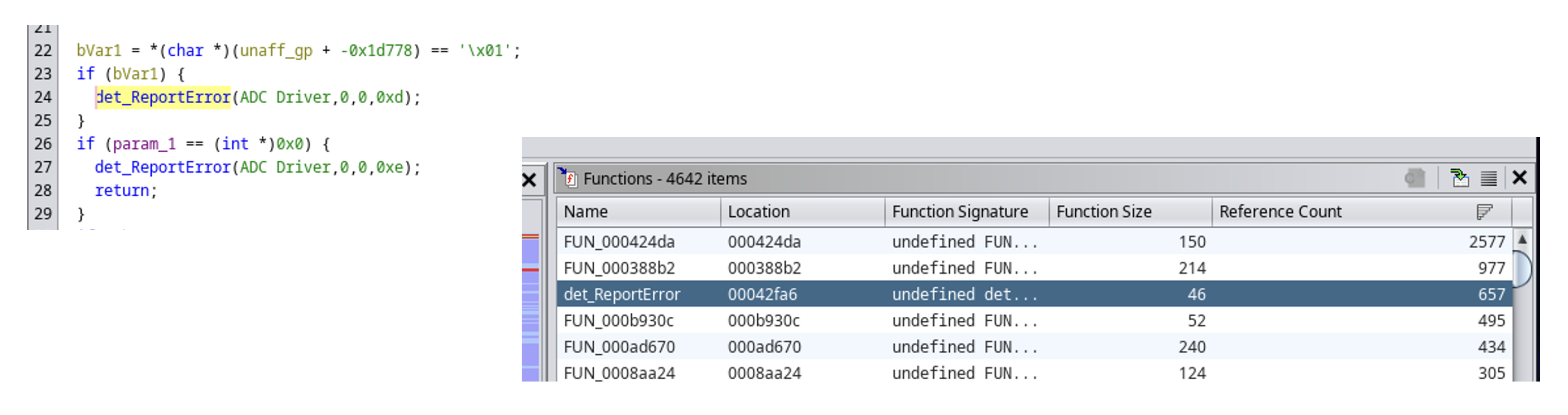 Decompiler view of a Det_ReportError call site with the four constant arguments inlined, and a comment showing the looked-up module and API name.
The process of determining which function called Det_ReportError can be automated with a Ghidra script that walks every xref to Det_ReportError, reads the four constants from the argument registers (or the stack, on architectures that pass them there), looks the IDs up in tables transcribed from the AUTOSAR specification, and renames the surrounding function. A complete implementation, including the lookup tables and the renamer, is published as autosar-re [3]. The underlying methodology is described in the SSTIC 2023 talk by Tillequin and Charron [4].
The same approach applies to any AUTOSAR API that takes constant module, API, or error IDs as arguments: Dem_ReportErrorStatus, Det_ReportRuntimeError, Com_SendSignal and Com_ReceiveSignal (signal IDs are constants in generated code), PduR_RxIndication (PDU IDs are constants), and the EcuM_* state APIs. Each labelled call site provides a fixed reference point that can be used to name a number of surrounding functions.