FlexRay
FlexRay was developed as a successor to CAN, with higher speeds (up to 10 Mbit/s) and fully deterministic behavior, making it suitable for drive-by-wire systems. It was developed by the FlexRay consortium and standardized as ISO 17458 in 2013 [1]. The FlexRay consortium disbanded in 2009.
It was used on vehicles from Audi, Porsche, BMW, Mercedes-Benz, and Volvo starting as early as 2006. It's unclear if any new vehicles from these manufacturers will still use FlexRay, as Automotive Ethernet is becoming more popular.
Physical Layer
FlexRay uses unshielded twisted pair cables to connect nodes on a bus. FlexRay supports both single-channel and dual-channel configurations for redundancy. Two or more nodes can be connected to the same bus, just like CAN.
Unlike CAN, only one node can be transmitting at a time. This means no arbitration is needed. When the bus is idle it's held high.
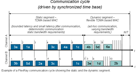 Example of a FlexRay communication cycle showing static and dynamic segments.
FlexRay Cycle
The FlexRay protocol is heavily inspired by TT-CAN and other time-triggered architectures. It uses a communication cycle consisting of the following parts:
- Static Segment: Reserved slots for deterministic data that is sent at a fixed time. Each node on the network has a space reserved in this segment for sending data.
- Dynamic Segment: Slot for event-based data that does not require deterministic timing. This segment behaves similarly to CAN. There is no arbitration or support for nodes sending at the same time. Instead, it uses a system of mini-slots. Each node is assigned a mini-slot in the dynamic segment. If a node has data to send, it will wait for its mini-slot (typically 1 µs) to begin sending the data. If a node decides to transmit data, the mini-slot counter stops until the transmission is complete.
- Symbol Window: Window used for network maintenance and signaling for starting the network. Either a Wake-Up During Operation Pattern (WUDOP) or Wake-Up Pattern (WUP) can be sent.
- Network Idle Time: A time window where the bus is idle. This is used to synchronize the nodes on the bus.
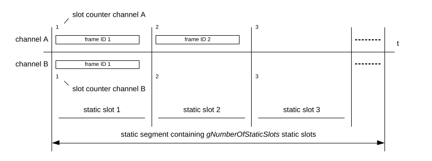 Structure of the Static Segment.
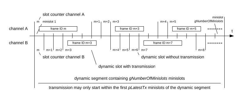 Structure of the Dynamic Segment.
FlexRay Frame
As discussed in the previous section, each node can send one or more frames in a cycle. The frame itself consists of three parts: the header, payload, and trailer.
Frame Encoding
Each frame consists of the following bit sequences:
- TSS (Transmission Start Sequence):
0 - FSS (Frame Start Sequence):
1 - For each byte m:
- BSS0 (Byte Start Sequence 0):
1 - BSS1 (Byte Start Sequence 1):
0 - Byte m, bits 0 through 7 (8×)
- BSS0 (Byte Start Sequence 0):
- FES (Frame End Sequence):
0 - TES (Transmission End Sequence):
1
The TSS is repeated between 1 and 15 times, depending on the bit rate. The edge between BSS0 and BSS1 is used for clock synchronization. This means no bit stuffing is required as in CAN.
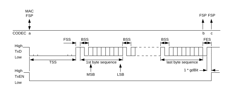 FlexRay bit level frame encoding.
Frame Structure
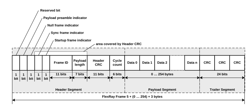 Structure of a single FlexRay frame.
Header
The header consists of the following fields:
- Status Bits: The header starts with 5 status bits, which are used to indicate the type of frame. See ISO 17458-2 [2] for more information on these bits.
- Frame ID: An 11-bit ID between 1 and 2047. This ID indicates the slot the message is sent in.
- Payload Length: A 7-bit field indicating the length of the payload in two-byte words. This allows up to 254 bytes of payload.
- Header CRC: CRC computed over the header fields transmitted so far.
- Cycle Count: A 6-bit counter that is incremented by one each communication cycle. This counter is used to detect missing frames.
Payload
The payload contains up to 254 bytes of data. The payload size is always a multiple of two.
For frames sent in the dynamic segment, the first two bytes of the payload function as a Message ID to identify the payload.
Trailer
The frame is terminated with a 24-bit CRC computed over the header and payload fields.
FIBEX Network Description
The FIBEX (Field Bus Exchange) format is used to describe the network. It is an XML-based format that describes the network topology, the ECUs on the network, and the messages that are sent. It functions both as a description of which slot is assigned to which ECU and as a replacement for a DBC file describing the signals within the payload.
Analyzing FlexRay Traffic
Saleae Logic 2
The outputs of the FlexRay transceivers can be hooked up to a logic analyzer to capture traffic. To make decoding easier we built an open source FlexRay decoder for Saleae Logic 2, available at github.com/I-CAN-hack/flexray-analyzer. It performs symbol recognition, splits each frame into its header, payload, and trailer fields, and verifies both the header and frame CRCs.
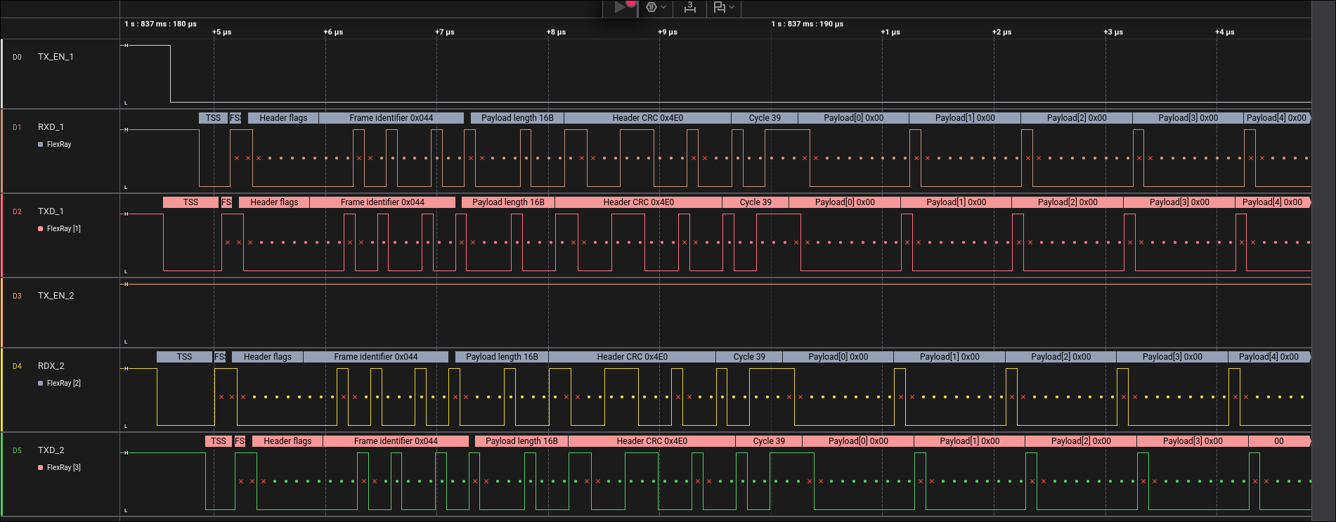 Saleae Logic 2 showing FlexRay traffic decoded into TSS, header fields, cycle count, and payload bytes.
PulseView
If you don't have a Saleae, PulseView, the GUI front-end for sigrok, ships with a FlexRay protocol decoder that works with a wide range of logic analyzers. However, the interface and parsing are slower, so it doesn't work well for large captures of multiple FlexRay channels.
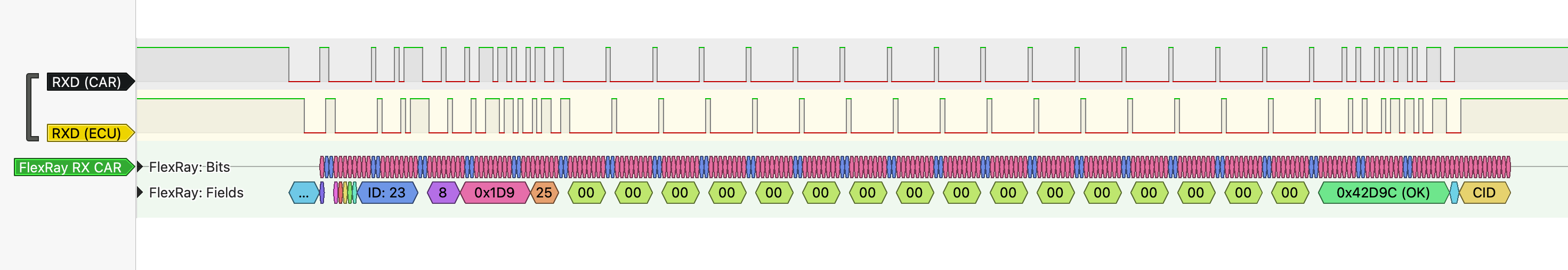 PulseView decoding a FlexRay frame into bits and fields, showing the frame ID, payload length, cycle count, payload bytes, and CRC verification.
Practical Attacks
Man-in-the-Middle Attack (MITM)
Given the strict timings involved in FlexRay communication, a MITM is not as simple as for CAN. It could be possible to use two FlexRay controllers to act as a MITM, but this would require obtaining the FIBEX file or reverse engineering all the timings in the network. This would also delay the messages by a full FlexRay cycle, which can be detected by the ECUs on the network by measuring the round-trip time of messages.
It's also possible to use an FPGA to modify the FlexRay packets while they are being sent. This requires detecting which packets are being sent and modifying them in real time. Since the header is controlled by the original ECU sending the frame, the CRC in the trailer has to be recomputed on the fly. This is a non-trivial task, but has been applied in practice to overwrite the ADAS signals sent to the ECU controlling the steering wheel in an Audi Q8.
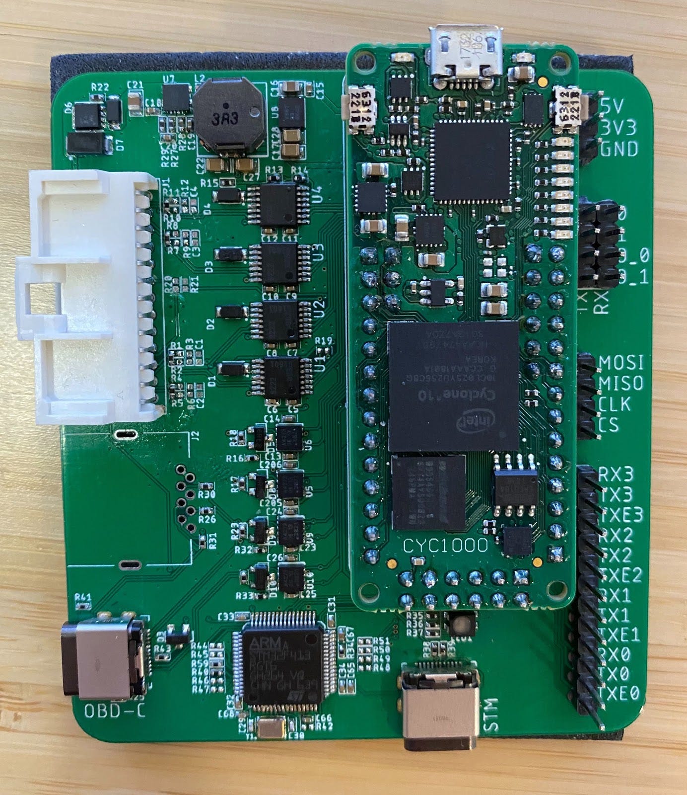 FlexRay MITM development board built around a CYC1000 FPGA, with four FlexRay transceivers and four CAN transceivers.
This board splits the FlexRay bus electrically and proxies frames between the two sides, with the FPGA implementing the FlexRay PHY so individual bits can be rewritten as they pass through. See the Audi FlexRay MITM writeup for the full build and results.
This can be mitigated by placing an extra CRC in the payload section, before the data. This way the CRC can't be computed before the rest of the data is known, requiring delaying the message by a full cycle. This delay can then theoretically be detected by the ECUs.