
Introduction
This is the fourth and final part in this series on attempting to modify the firmware running on an Electronic Power Steering (EPS) ECU from a 2010 Volkswagen Golf. The goal is to modify the firmware to remove a 6 minute lockout on lane keep operation and allow use of lane keep at low speeds.
In the previous part, I identified the changes I wanted to make to the firmware. In this part I’ll focus on flashing the patches to the actual module. First, I’ll use Can Calibration Protocol (CCP) to extract the bootloader from the module. Then, I’ll reverse engineer the bootloader to figure out how the flashing procedure works. Finally, I’ll apply the patches to an actual car and verify they work.
Extracting the bootloader
In an earlier part, I used an update file to extract the application firmware and used that to identify the patches I want to make. However, that update file only contains addresses higher than 0xa000, while the bootloader probably lives before that. When entering the “programming” diagnostics mode the application will restart and jump to the bootloader code at the beginning of flash. Interestingly enough, you don’t need any passwords to enter this programming mode. When trying this on the actual module I observe that the regular CAN messages stop being outputted, and I can only send a limited number of KWP2000 requests indicating this is indeed a different application that’s running.
In order to figure out how the flashing works exactly, I needed to dump the bootloader from an actual ECU. Usually once you have the application firmware it’s not too hard to find an arbitrary read, and dump the remaining code. I’ve seen things from a complete text based shell, UDS routine controls that allow requesting memory contents, or leaving CCP/XCP enabled.
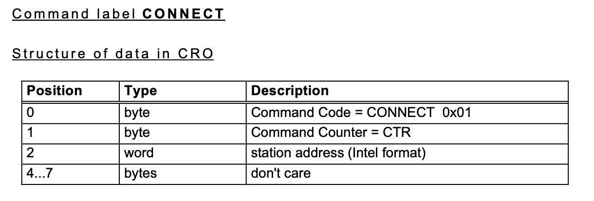
In this case, we’ll go through the CAN parsing functions found in the previous part and we quickly see something resembling CCP on addresses 1746 and 1747 (tx/rx), with a handler function on 0x00011152. It allows connecting using station ID 0x0 and 0x815. The required functions to interact with raw memory (DNLOAD, UPLOAD and SET_MTA) are implemented, and don’t have any bounds checks. None of the key/seed parts of the CCP standard are implemented, so no authentication is required either.
 Untitled
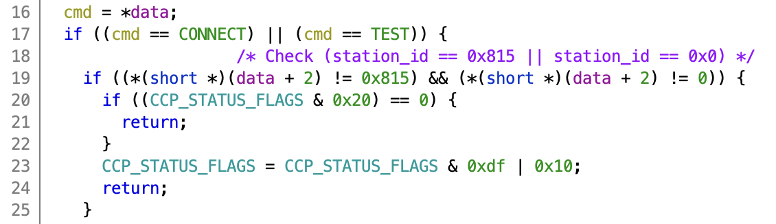 Connect part of the CCP handler function. Note station ID 0x0 and 0x815 are valid station IDs.
Connect part of the CCP handler function. Note station ID 0x0 and 0x815 are valid station IDs.
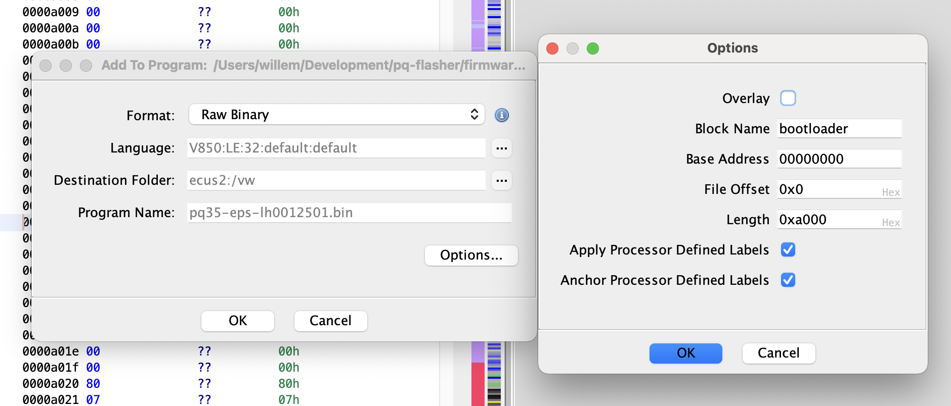
Using the CCP library in panda it’s easy to throw together a script to dump the complete memory contents. This also allowed me to verify that the code running on the ECU matches the firmware from the update file I have been reverse engineering. After dumping the whole flash we can replace the bootloader area (0x0 - 0x9fff) by the file I just dumped using File → Add To Program. After that I re-ran the auto analysis.
 Untitled
Flashing procedure
After loading the bootloader into Ghidra I need to identify the KWP2000 handler in the bootloader. I apply the same method by looking for KWP error codes. In this case we expect to find flashing code, so I searched for return 0x41 (improperDownloadType), and found the handler at 0x00008c64.
Flashing an ECU usually follows the same general steps, and I expect to find something similar when reverse engineering this firmware:
- (optional) Log in with a key/seed using
securityAccess - Entering the bootloader using
diagnosticSessionControl - (optional) Log in again with a key/seed using
securityAccess - Start the flashing using
requestDownload. Sometimes called after erasing - Erase memory using a
routineControlcall (0xFF00for UDS) - (optional) set a decryption key if the firmware is sent encrypted to the ECU using
writeDataById - Send the data in chunks using
transferData - Indicate all data has been sent using
requestTransferExit - Make the ECU verify the checksum and mark the firmware as bootable using a
routineControl(0xFF01for UDS) - Reboot the ECU using
stopCommunicationorecuReset
I will expand on each step below. You can also follow along in the flashing script I wrote which implements all these steps.
Entering bootloader
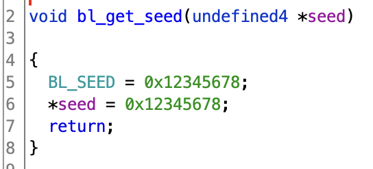
In this case we don’t need to go through any securityAccess in the application firmware and can reboot straight into the bootloader by requesting diagnostic session 0x85. Once in the bootloader we do have to go through a securityAccess, but the seed is always 0x12345678 and the response is not actually checked. You do have to actually go through the steps of requesting a seed and sending the key though, otherwise the flashing state machine doesn’t proceed to the next step.
 Untitled
Request download
The actual flashing is started using requestDownload . This includes the start address, size, compression type (uncompressed - 0x0) and encryption type (unencrypted - 0x0). The packet is laid out as 0x34 (requestDownload) - start address (3 bytes) - compression & encryption (1 byte) - number of bytes (3 bytes).
Erase flash
The flash is erased using routineControlByLocalIdentifier with routine identifier 0xc4. The start and end address (inclusive) are passed in as well. The bootloader then checks if the given addresses match the start address and size sent in the previous step. If they match it starts erasing the flash. The erase operation can take quite a while, and the ECU won’t respond in the meantime. Therefore we keep trying to open a new TP 2.0 channel, until the ECU responds again.
After re-establishing a connection, we need to check if the erase was sucesfull. This is done using requestRoutineResultsByLocalIdentifier with the same routine identifier (0xc4). If the erase was sucessfull 0x0 will be returned.
Transfer data
After erasing, it’s time to send over the new firmware. This is done in chunks. The maximum chunk size is returned by the requestDownload call, in this case 0xf1 (241) bytes per chunk.
After all the chunks have been sent the transfer is finished using requestTransferExit. This also check if the right amount of data has been sent based on the ranges request earlier.
Compute checksum
After flashing, the checksum of the data must be sent as a sanity check and to ensure no data was corrupted in transfer. Just like the erase this is done using routineControlByLocalIdentifier with identifier 0xc5. We then need to check for success using requestRoutineResultsByLocalIdentifier. The checksum itself is just a sum of all the bytes transferred, truncated to two bytes.
Some ECUs also verify that the firmware has a valid signature at this point, but that does not seem to be the case for this EPS. While testing other potential patches I made small code changes to the EPS on my desk and it booted up just fine. From what I have observed this seems to be more common for the German brands than on Japanese cars. Make sure to check out these interesting posts by Brian Ledbetter and JinGen Lim on this subject!
Stop communication
After all the flashing is done (it’s possible to repeat these steps multiple times for different blocks), it’s time to reboot the ECU by sending stopCommunication. If all the flashing steps were successful this will write a special marker 0x65646e45 (”Ende”, German for end) to the end of the flash, this indicates to the bootloader that the application is valid and can be booted. If flashing failed for some reason, it won’t try to start a potentially corrupted application but will stay in the bootloader. When flashing back a dump obtained using CCP it’s important to remove this marker, so we don’t accidentally mark the flash as valid when flashing might have failed.
Conclusion
We now have all the moving parts to actually reflash the ECU with the desired changes. I made a GitHub repository which contains the necessary scripts, and helper libraries implementing TP2.0 and KWP2000: https://github.com/I-CAN-hack/pq-flasher.
Only try this on an actual car if you know what you're doing. Even though only two very small patches are made to the model specific calibration values, making changes to your EPS might have unintended consequences. You can lose power steering, or the steering motor may put large amounts of torque on the wheel unexpectedly. Ensure the patches to the calibration values are safe before using.
The flashing procedure consists of roughly three steps.
- Dump the existing firmware + calibration using CCP. Technically it’s possible to use the update files to skip this step, but this ensures the exact same firmware is flashed back. This needs to be done using a direct connection to the EPS, and can’t be done through the OBD-II port since there is a gateway that blocks the CCP addresses. For example, this can be done using a J533 harness. This step takes about 15 minutes.
- Applying the patches. The patching script will change the minimum speed and HCA timer. It verifies it’s patching the right firmware version based on the version string, and checks the existing values before changing them.
- Flashing back. You can choose to flash back the whole firmware, but this is not recommended since this takes about 10 minutes, and can risk bricking the ECU if you apply the wrong patches. By default the flasher script will only overwrite the calibration area that contains the values we actually changed.
Hopefully, this series of blog post will be useful reference for people getting started with car hacking. There is a lot of similarity between ECU firmwares from different cars and these posts should allow people to learn from my experience (and mistakes).
 IMG_3189.HEIC
All posts in this series: