
Introduction
This is the second post in this series on attempting to modify the firmware running on an Electronic Power Steering (EPS) ECU from a 2010 Volkswagen Golf. In the previous part, I obtained a copy of the module, and did some preliminary research. In this part, I'll describe how to obtain the application firmware running on the ECU.
First, I tried to extract the firmware over the CAN bus, but did not succeed. However, this resulted in some knowledge on how to brute-force the authentication and enter a password protected diagnostics mode.
Second I'll describe how I found a VW upgrade file and decrypted1 it. Finally, I will load the binary into Ghidra and make some initial guesses at the architecture and memory map of this unknown microcontroller.
KWP2000 - ReadMemoryByAddress
Since I can already talk to the ECU over the KWP2000 diagnostics protocol, the next step would be to try using the RequestUpload or ReadMemoryByAddress service. Unfortunately, the RequestUpload service was not available. Trying ReadMemoryByAddress resulted in an access denied error. However, this is good news as it means the endpoint does exist, but can only be accessed from a different diagnostics mode than the default (0x89).
Not all diagnostics modes can be entered immediately, some require going through a log in procedure. In KWP2000 and UDS this is done by requesting a "seed", performing some kind of computation to turn the "seed" into a "key" and sending it back to the ECU. In my experience this can be anywhere between 1 and 8 bytes, and the computation varies from a single xor to some more complex cryptography.
Luckily for me the OBD11 software has a log in function, and very helpfully suggests a default password that allows access to some (but not all) diagnostics modes. By observing OBD11 perform a few seed-key procedures I could deduce the seed/key is 4 bytes in length. Also, to turn to seed into the key you simply add the password. Unfortunately, the default password still doesn't allow entering the "engineering" mode (0x86) which will hopefully give access to ReadMemoryByAddress.
Therefore, the password required for the engineering mode needs to be brute-forced. The OBD11 app accepts passwords up to 65536, so it seems like the space is only two bytes large, which should be enumerable in reasonable time with a few guesses per second. Usually, ECUs have some protections against brute forcing the seed/key algorithm. This often comes in two parts. First, there is a timeout after booting the ECU before a seed can be requested. Second, after one (or sometimes three) attempts you will be locked and need to power cycle the ECU. This EPS seems to allow requesting seeds immediately after boot, but it stores the number of wrong tries in non-volatile memory which are only cleared after about 10 minutes of runtime.
Luckily, there is a bug and the number of wrong tries is cleared no matter which password is used to log in with. Since a valid password (with less privileges) is known, you can alternate between the brute-force guess and the known good password, and never trigger a lockout.
I wrote a small script on top of the KWP2000 library written earlier to perform this brute force attack. This script can be found in the GitHub repo for this blog series: brute_force_pasword.py. After a few hours of brute-forcing this gave two new passwords where one allowed access to engineering mode.
My guess about ReadMemoryByAddress being accessible from this other diagnostics mode was correct, and I was able to request some data from the ECU. However, I could only request up to address 0x400 , this data returned contained a valid VIN. We can assume that this endpoint is probably used to read the contents of non-volatile memory for debugging purposes2, and won't get me closer to a firmware dump.
Update files
Another way to find the firmware for an ECU is trying to find update files from the manufacturer. Sometimes updates are released to fix a bug, or the same hardware is used in different cars that need to run different software. If you get lucky, the manufacturer tool contains an update file. You can then either try to extract the raw firmware from whatever compressed or encrypted container format the manufacturer is using, or flash an actual ECU and sniff the firmware of the CAN bus. The latter is not always possible, since a decryption might happen on the ECU side, unless you already know how the decryption process works.
I found this nice website where I can enter the part number (1K0909144E) and it will tell me the firmware file to look for: lh0022901.sgo. You can search the VW flash disks for this filename. The file is present, but unfortunately too small to contain anything interesting. However, some more googling pointed me to lh0012501.sgo and lh0013501.sgo. The 2501 firmware is a bit harder to find, so you can also use the 3501 if you're following along. So in this case I got lucky, and (part of) the firmware could just be downloaded online.
Now that we have the firmware in this unknown .sgo format, it's time to figure out how to extract it. A quick search shows it's some custom format, so we're mostly on our own. The first step is to run strings on the file. Usually an ECU firmware contains at least a few strings with the version and part numbers. Besides the header SGML Object File, there are no ascii strings in the file. The next step would be run binwalk and see if that recognizes any known magic signatures:
$ binwalk lh0012501.sgo

DECIMAL       HEXADECIMAL     DESCRIPTION
--------------------------------------------------------------------------------
That also comes up completely empty. So no standard compression formats are used. Binwalk can also draw a graph of the entropy, which might tell us more about this file.
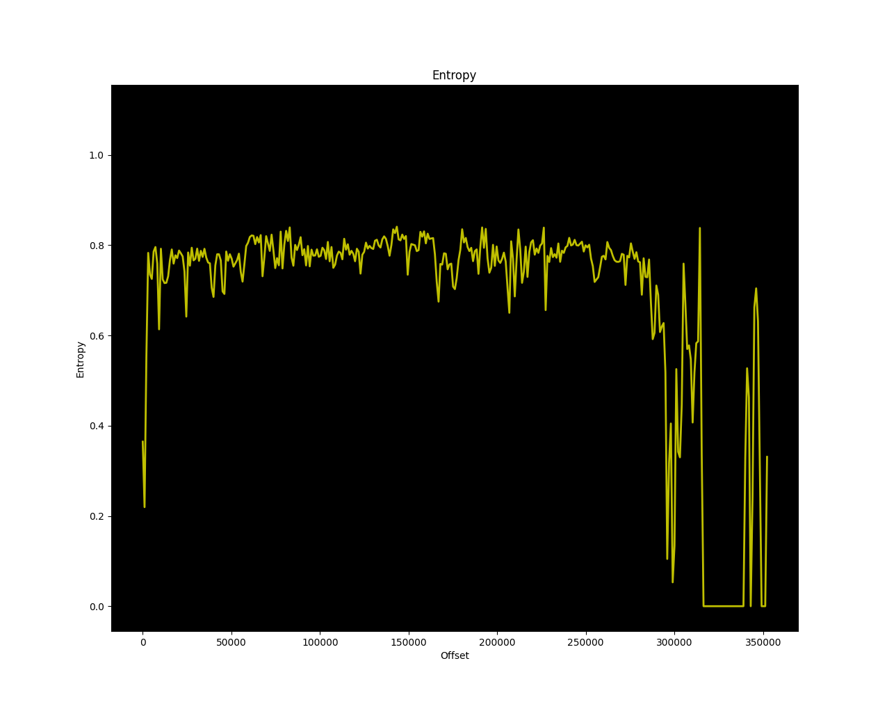
That's some good news! The entropy of most of the file is around 0.8, which means we're probably looking at code! Later in the file the entropy is a bit noisy and goes all the way to zero. That's probably some more structured data with lookup tables or just zeroes. The fact that the entropy is not close to 1 means it's not compressed or encrypted. However, strings didn't return anything so we're probably dealing with a simple xor cipher here.
After looking at a hexdump of the file a bit more, I noticed there are large areas that contain only 0xff. Are those areas with zeroes in the original file? Did VW xor everything with 0xff? Let's find out! A simple python one-liner will write out a copy of the file: python -c "open('lh0012501.sgo.out', 'wb').write(bytes([c ^ 0xff for c in open('lh0012501.sgo', 'rb').read()])"). After running strings on the produced output we now get some useful strings including a build date. Success!
$ strings lh0012501.sgo.out
  <snip>
EPS_ZFLS Kl.
STG_Lenkhilfe
  <snip>
EPS_ZFLS Kl.
370300D0601
370300D0601_T00
gx0630
2008/08/01 08:59:24.22
7805079363
370300B0201
?W  =
B1B3B9D1GKIDKOHCM1HYPLLWPDDUDDFTPRSEERDMOF
PREDRIVE
DRIVEUP
DRIVEDOWN
FACTORYTEST
POSTRUN
SERVICE
ERROR
DIAGMODE
  <snip>
Besides strings we can also check if the file contains valid instructions using cpu_rec, which recognizes a chunk of V850 code.
$ ./cpu_rec.py lh0012501.sgo.out
full(0x562a2)  V850                               chunk(0x37000;110)  V850
So, after confirming the update file contains actual code it would be nice to know a little bit more about it. After doing some more research I found a (now discontinued) tool called VAGHelperX that can give some more information about the contents of the file and also allows to extract the individual parts of the .sgo as binary or (broken) Intel HEX. Maybe I'll write a python parser/packer for .sgo files in a later blog post, since it would be nice to not have to rely on proprietary software and also be able to create new .sgo files after making modifications. This could also be turned into a Ghidra loader to load up .sgo files directly.
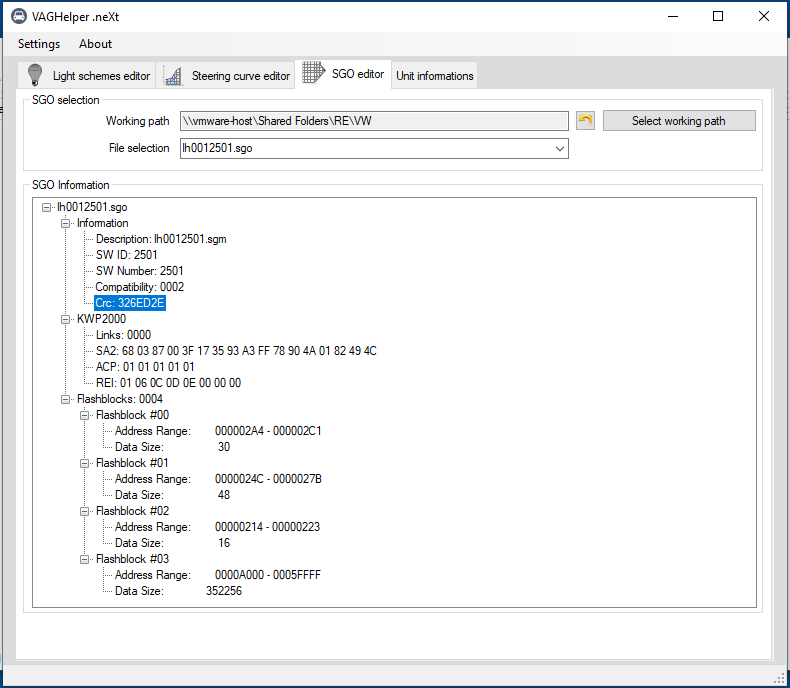
VAGHelper shows that the .sgo file consists of four parts of which three are pretty small. The actual firmware is probably contained in the range from 0xa000 to 0xa5ffff. This also means this update spans most of the flash memory, and only the part from 0x0 to 0x9fff is not contained in this update. This lower part of the firmware probably contains the bootloader that is used to actually flash the update, but more on that in a later blog post. It's nice that VAGHelper shows the offsets in flash, since that will help with loading the generated binaries at the correct offsets in Ghidra.
Can Calibration Protocol (CCP)
I didn't need to use this method at this point in the process, since I already had enough of the firmware from the update file to get started with reverse engineering. However you might not get this lucky and there are no update files available.
As an alternative to KWP2000 or UDS, you can use some more obscure protocols to extract firmware over CAN: CCP and XCP. Can Calibration Protocol (CCP) was introduced in 1999 and later followed up by the Universal Measurement and Calibration Protocol (XCP) which can also be used over CAN-FD or Ethernet besides regular CAN.
CCP/XCP are used by the developers of the ECU to read out values, or make adjustments while testing the ECU in a car. For us car hackers, the most interesting functionality is the ability to read and write memory. A lot of intermediate values are stored in global variables for debugging purposes, that can be read and plotted live using CCP. The addresses of the global variables are stored in an A2L file that can be loaded in by something like CANape, similar to a DBC file for CAN packets. It can also be used to update look up tables or tuning values while running the ECU.
If you can find this CCP interface, it might help in extracting the firmware or use it as a debugging tool when developing patches. It is possible to find the CCP/XCP addresses by brute forcing, but if very high CAN addresses or station IDs are used you might never find them. CCP/XCP also have similar log in procedure as KWP2000/UDS with a seed/key algorithm. So even if you find them you might be locked out.
The CCP CONNECT command is 0x01, followed by a counter (0x00 in this case), followed by a 2 byte station ID. Scanning for CCP is done by sending a CONNECT command to every CAN address and every possible station ID, and checking for a response. The search range is quite large, so I would recommend starting with addresses between 0x600 and 0x800 and station IDs below 64.
The XCP CONNECT command is a bit simpler and is just 0xff followed by the connect mode (0x00 for normal connect mode). No need to brute force a station ID.
In a later blog post I will revisit CCP to extract the bootloader, since I didn’t get that from the firmware update file.
Loading the firmware in Ghidra
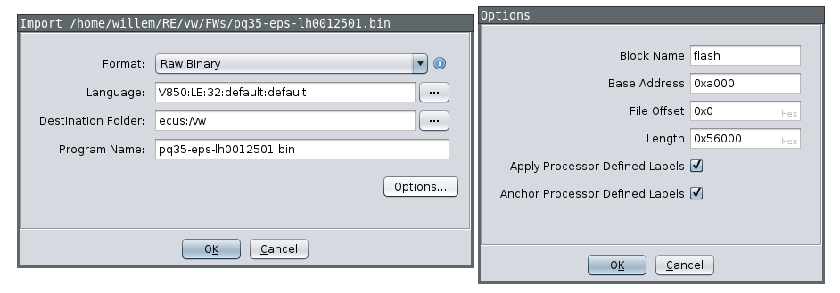
With a partial firmware update obtained, I can load this up in Ghidra. I already know the file needs to be loaded at offset 0xa000 and the CPU architecture is V850. Unfortunately there is a small bug in Ghidra, so I recommend applying a small patch as a workaround. Press no when asked to analyze when opening the file for the first time. After loading the file I also created an empty section from 0x0 to 0x9fff as a placeholder for the bootloader.
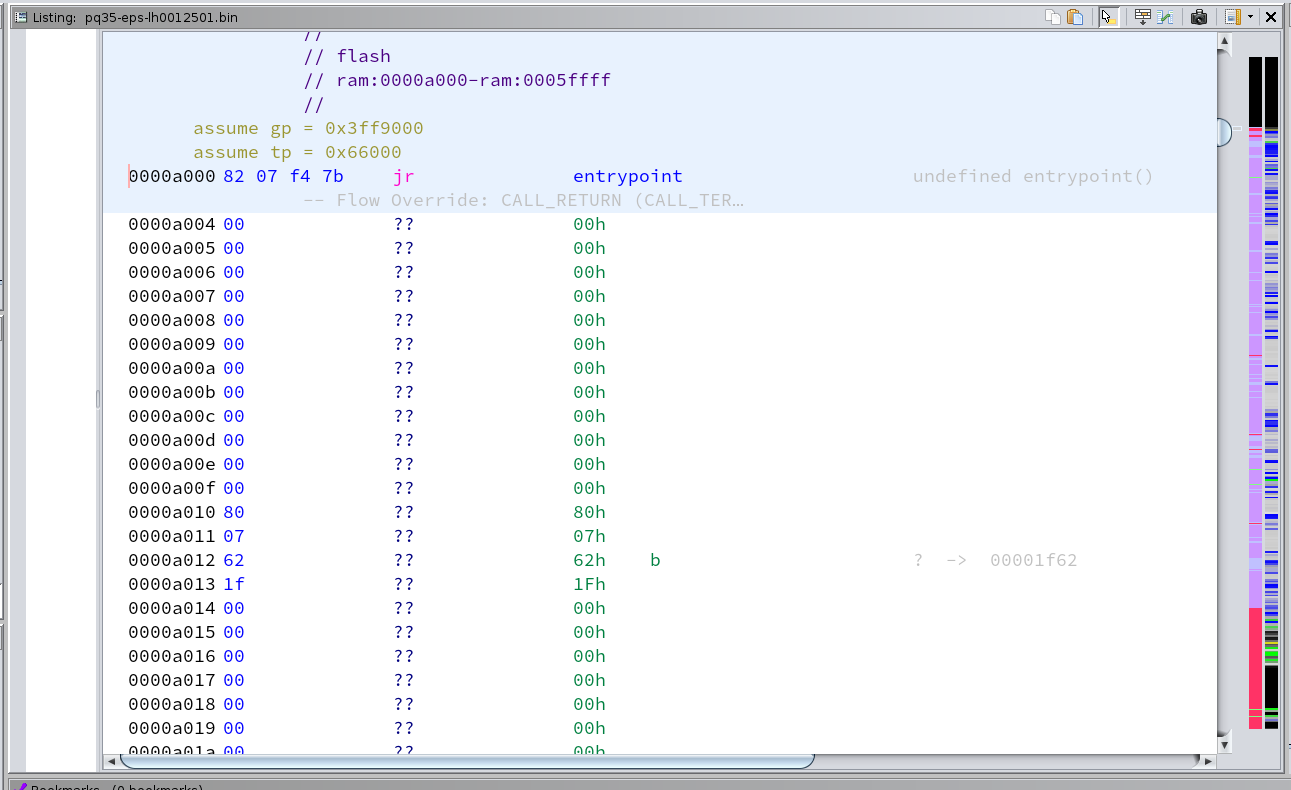
After loading up the file press d on the first instruction (0xa000) which should be a jump to the actual entrypoint of the firmware. Ghidra already marked some functions as code based off this, which we will use for the automated analysis later. But before we run that we need to make sure the tp (text pointer) and gp (global pointer) are set up correctly. tp is usually set to the end of the firmware or data section and is used to reference static data. gp points somewhere in RAM and is used as an offset for global variables. tp and gp are set up in the entrypoint. See the V850 reference manual for more information.
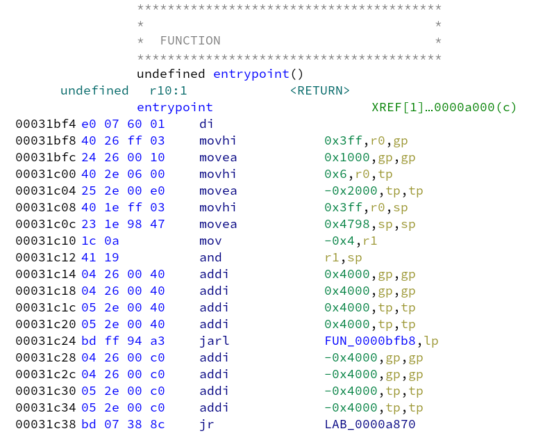
tp = 0x60000 - 0x2000 + 0x4000 + 0x4000 = 0x66000, gp = 0x3ff1000 + 0x4000 + 0x4000 = 0x3ff9000. Fix these register values by selecting the flash area, click right and select "Set Register Values". Now we can run the automatic analysis, but make sure to disable "Create Address Tables" since that will generate false positives inside code areas which interferes with discovering code areas.
The firmware is laid out as bootloader application firmware data. After running the automatic analysis we can see this structure appear in the sidebar3, but some data will be erroneously marked as code. So we can go in and clear all the found code after 0x50000 for now (right click, clear with options, select code and functions).
There are also some areas between functions that have not been marked as code yet. This code is probably not referenced by a jump, but might be called based on a data table somewhere. Mark these as code by hand (basically everything between 0xd000 and 0x4eaea) Some instructions of the form 0xe0 0x07 are not parsed correctly (probably a missing instruction in the V850 SLEIGH definition in Ghidra), so you might have to manually start disassembly again after skipping that instruction. After this your overview sidebar should look like this (code/data on the left, entropy on the right), and with the gp and tp registers set.
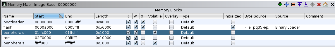
Scrolling around you can see lots of references to addresses that are not part of the memory map. These reference RAM (0x3ffXXXX) and Hardware Peripherals (0xfffffXXX and 0x01ffcXXX). Add these missing ranges to the memory map. For RAM I chose 0x3ff0000 to 0x3ffffff, and for peripherals 0xfffff000 to 0xffffffff and 0x01ffc000 to 0x01ffcfff. These ranges are probably larger than on the actual microcontroller but that shouldn't matter. Make sure to mark the peripheral range as volatile. After updating the memory map, run the auto analyze again.
Conclusion
In this part I tried to extract the firmware over CAN using KWP2000, however only managed to extract 1024 of config flash. I then managed to find and extract an update file, and load it into Ghidra. Using some educated guesses I reconstructed the layout of the firmware, peripherals and memory map. I'm ready to start actual reverse engineering process now!
In Part 3 I'll describe some general techniques how to find some starting points when starting to reverse engineer a firmware from scratch. I'll look for the diagnostics handlers, CAN parsing and find the actual function responsible for the 6 minute lockout and minimum speed checks.
All posts in this series:
- Part 1: Introduction and Diagnostic communications
- Part 2: Obtaining the application firmware
- Part 3: Reverse engineering and identifying the patches
- Part 4: Obtaining the bootloader and flashing the patches
Footnotes
- If you would call an xor with 0xff encryption ↩
- This non-volatile configuration area is often referenced as EEPROM, but is usually emulated by reserving an area in flash ↩
- I always enable the entropy and code/data markers in the sidebar using “Show Entropy” and “Show Overview” since it gives a clear overview about the layout of the firmware. ↩