
Introduction
In this series of blog posts I'll describe my attempts at modifying the firmware of an Electronic Power Steering (EPS) ECU from a 2010 Volkswagen Golf Mk6. This steering rack is probably present in all VW PQ platform cars, starting from 2008 up to the present day. Cars from the PQ46 platform are still being produced (e.g. the 2022 Pasat NMS). This probably means this is one of the most produced EPS modules in the field.
Even though the rack was introduced back in 2008, support for Lane Keep Assist (LKAS) or Heading Control Assist (HCA) in VW terminology, is already present. This makes it possible to use this car with openpilot, an open source driver assistance system. Unfortunately, steering commands are not accepted after 6 minutes of continuous operation or below 50 km/h. At that point you need to disengage for a full second. I believe these measures are counter-productive, and compromise safety when a proper camera based driver monitoring system is already in place. Therefore, I wanted to make some modifications to the firmware running on this EPS to disable them.
During my previous car hacking projects, and working on this VW ECU, I noticed there are very few good resources on the internet that describe the whole process from getting an ECU running on your desk to flashing modified firmware. In this series of blog posts I'll describe my journey hacking this ECU, including dead-ends and detours. For each part, I'll also give some context that might apply to other ECUs or other brands.
In this first part I’ll get a second ECU running on my desk, and will establish diagnostic communications. In part two I will fail to extract the firmware from the module, but will find a firmware update file and load that into Ghidra after decrypting it. In part three I’ll describe the actual reverse engineering process, and identify the patches I want to make to the firmware. In the fourth and final part I’ll extract the bootloader from the ECU, and describe the flashing process.
Only try this on an actual car if you know what you're doing. Even though only two very small patches are made to the model specific calibration values, making changes to your EPS might have unintended consequences. You can lose power steering, or the steering motor may put large amounts of torque on the wheel unexpectedly. Ensure the patches to the calibration values are safe before using.
All the code written to communicate with the ECU, and eventually reflash it are open source and can be found here: https://github.com/I-CAN-hack/pq-flasher. Note that this is a personal project, done on my own time and not related to my work at comma.ai.
 IMG_3189.HEIC
Obtaining the parts
The first step to hacking an ECU would be to obtain one (or more) of the ECU in question1. For this, we need to obtaining the part number. If the ECU is in an accessible place, the part number can usually be read from the module. If the ECU is buried deep inside the car you might be able to find it on the manufacturer parts website or on Ebay2.
Alternatively, if you want to be 100% sure, you can use a diagnostics tool to interrogate the ECU over CAN. Usually, it's able to directly report you its own part number. In this case , the latter method was used, and the part number is: 1K0909144E.
With the part number in hand, we can look for second hand parts. The older and more sold the car, the easier and cheaper this will be. Depending on your location you might have to look on a few websites. In the US I had the most luck with Ebay and LKQ Online. In Europe shipping might make Ebay more expensive than sourcing something local. Just Googling the part number might turn up some results. For this project, I found one on onderdelenlijn.nl, and picked it up a few minutes from my home. I only paid €100 for a whole rack since this is such a common car/part. For more recent cars you can expect to pay up to $200-$500 depending on the type of ECU.
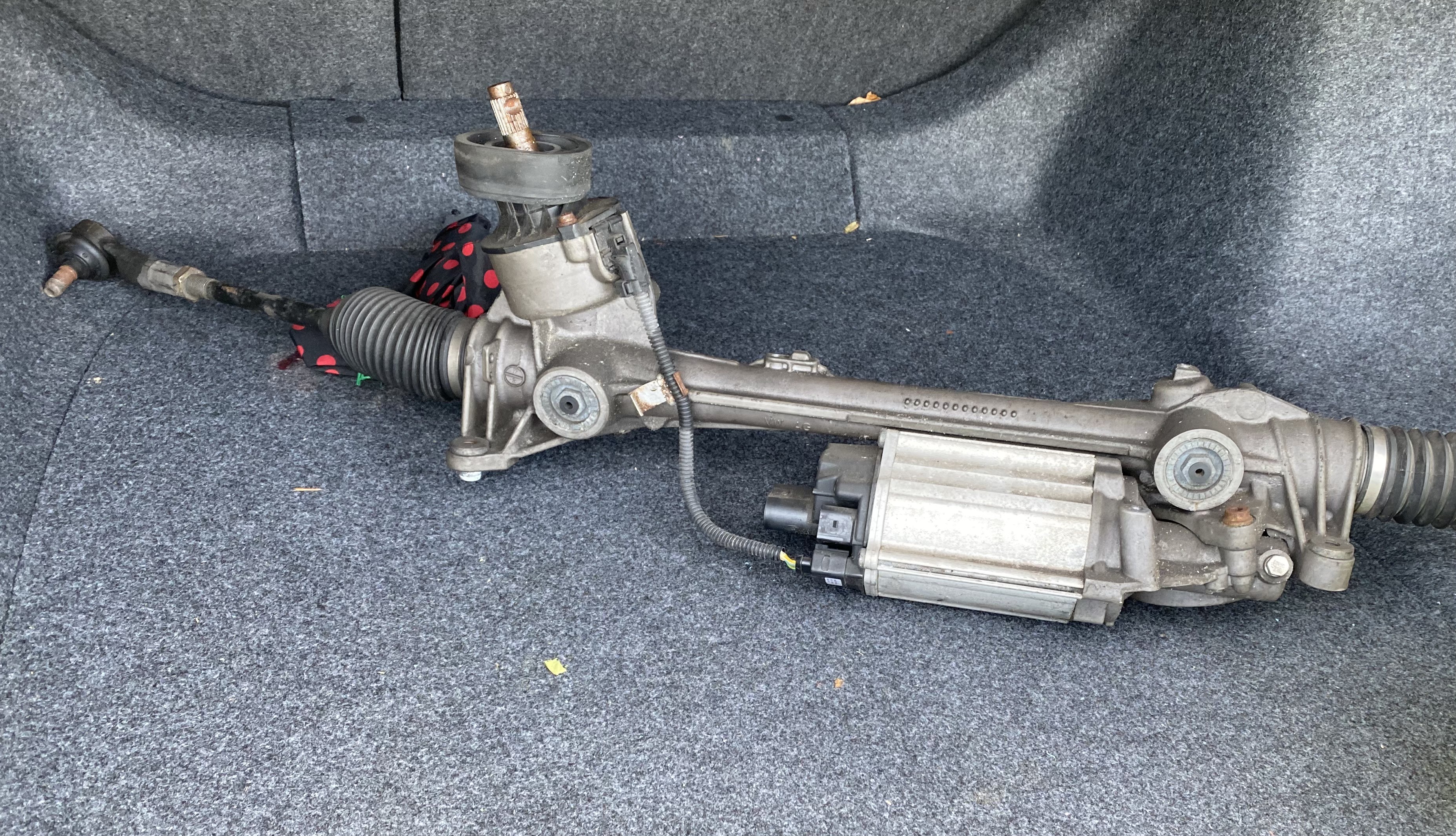 My newly obtained rack in the back of my car
Taking things apart
Now that we have have a duplicate of the ECU we're interested in, we can have a closer look at it. Our first goal is to get it up and running and talking to it over CAN, to ensure it still works. Second, we'd like to connect a debugger to the microcontroller inside to see if we can extract the firmware in case debug access was not disabled3.
To connect to the ECU we have to find the pinout of the connector. This can usually be obtained using the original schematics. Most car manufacturers offer a subscription service to all their manuals and schematics, usually with a cheap 1-day option (e.g. Toyota TIS, Honda Techinfo, and VW Erwin). The premium subscriptions usually also come with the original diagnostics software, which can be used with any J2534 dongle such as a panda or Tactrix.
In this case, after connecting it to a panda and running a simple dump tool, we were presented with some nice CAN traffic. We can match this to the corresponding Golf DBC file and confirm that these are indeed messages sent by the EPS (Lenkwinkel_1, Lenkhilfe_3, Lenkhilfe_1, and Lenkhilfe_2).
hex  ( dec) data
0x0C2( 194) b'0000000080224bdd'
0x0D0( 208) b'44b0002004d0'
0x3D0( 976) b'00a10028005d'
0x3D2( 978) b'52411200010000'
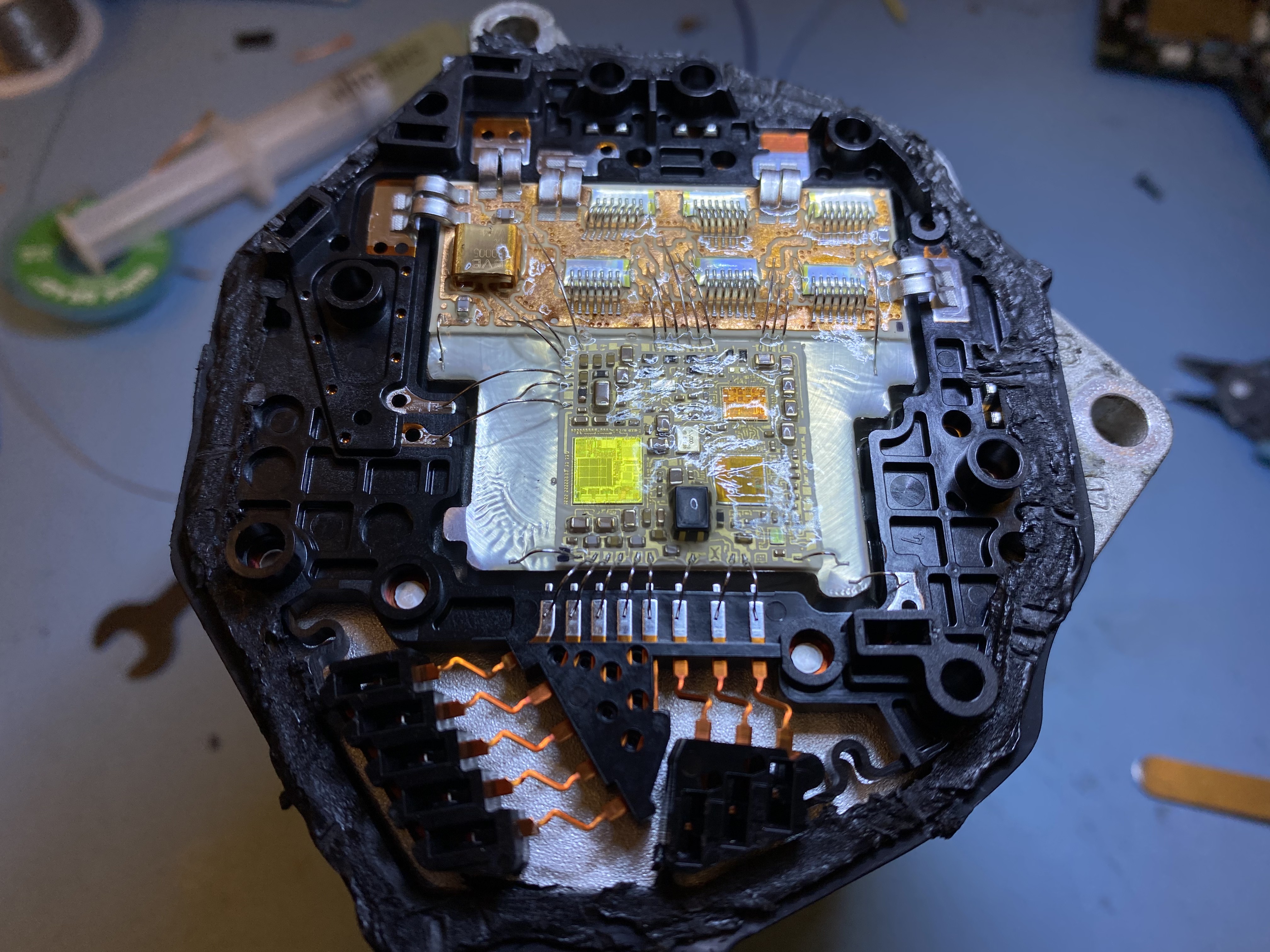
After establishing communication and ensuring the module is alive, we wanted to take a look inside to see what we're dealing with. However, after opening it up I was presented with a little surprise. The electronics seemed to be fabricated using bare dies attached to some substrate, probably to lower cost and improve reliability at higher temperatures. The board is made up of two parts, a low-power part with the CPU and CAN transceivers, and some high-power part with 6 MOSFETs forming a three phase H-Bridge.
 IMG_3181.HEIC
However, this meant that we have no part number to look for a datasheet, and no way to attach a debugger. The yellow-ish die is probably the main CPU die, but the markings (CL220CA) don't show up in google. If anybody recognises this CPU I'd love to know more about it!
Since we don't know what exact microcontroller we're dealing with, and there are no connections exposed to hook up a debugger in the first place, we can't move forward with this approach. To learn more about this ECU we have to do more exploration using the available CAN interface.
Although we don't have a part number for the CPU we can still make a few educated guesses. Only a few different CPUs are used in ECUs, especially in power steering motors which require ASIL D rating (the highest requirements on safety). These microcontrollers usually have multiple cores running in lock-step tied with an external watchdog to provide redundancy. The options are basically:
- Infineon TriCore. Such as the TC2xxx. I've seen these pop up recently in newer Hyundai ECUs. If they leave JTAG enabled, which was the case in the ECUs I looked at, you can easily dump those with a miniWiggler.
- Power PC. Such as the ST/NXP/Freescale MPC5xxx or more recently S32R2x4. Can be dumped using a Multilink.
- V850. Such as the Renesas PD70Fxxxx. Can be dumped through their built in bootmode. I never had much luck using the windows flash tool, but there is good python implementation.
- ARM. Such as the NXP S32K3. This seems to be a very recent line of microcontrollers and I haven't seen this in actual ECUs yet. You only might see it in a few years due to the long development cycle of automotive electronics.
- C166. Such as the XC164CS, but this architecture seems to be discontinued. Can be dumped by sending a special dumping script to CAN bootloader.
Usually the connections needed to attach a debugger are exposed using an unpopulated pinheader or bare pads scattered around the PCB. Using the data sheet and a multimeter you can figure out how to attach the debugger.
If the microcontroller is in a BGA package and the pins are not exposed you can use a JTAGULATOR to "bruteforce" the debugger pinout. If that doesn't yield any results you can sacrifice another ECU by desoldering the BGA component.
CAN Diagnostics
As we already have the ECU connected to a computer using a panda, we can try to figure out if we can talk to it over one of the standardized diagnostics protocols such as UDS or its predecessor KWP2000. UDS/KWP2000 have many useful "endpoints", including reading memory, so this would be a good place to start.
We can start by running a small scanning script. This will send the UDS "Tester Present" command to the most commonly used diagnostics addresses (0x700 - 0x7ff, 0x18da00f1 - 0x18dafff1). However, this didn't return any hits. This means UDS/KWP2000 is not used, at least not using the standard transport ISO-TP.
Since CAN messages can only contain 8 bytes usually a transport layer is used between the diagnostics protocol and the raw CAN messages to transfer larger chunks of data. Most ECUs use ISO-TP, which uses the first byte in every message to indicate its sequence counter and if more messages will follow. It also contains some flow control for cases where the receiving ECU is not ready to receive yet. For diagnostics in the 0x7XX range responses are usually sent on TX address + 0x8, for messages in the 0x18daXXf1 range the last two bytes of the address are swapped.
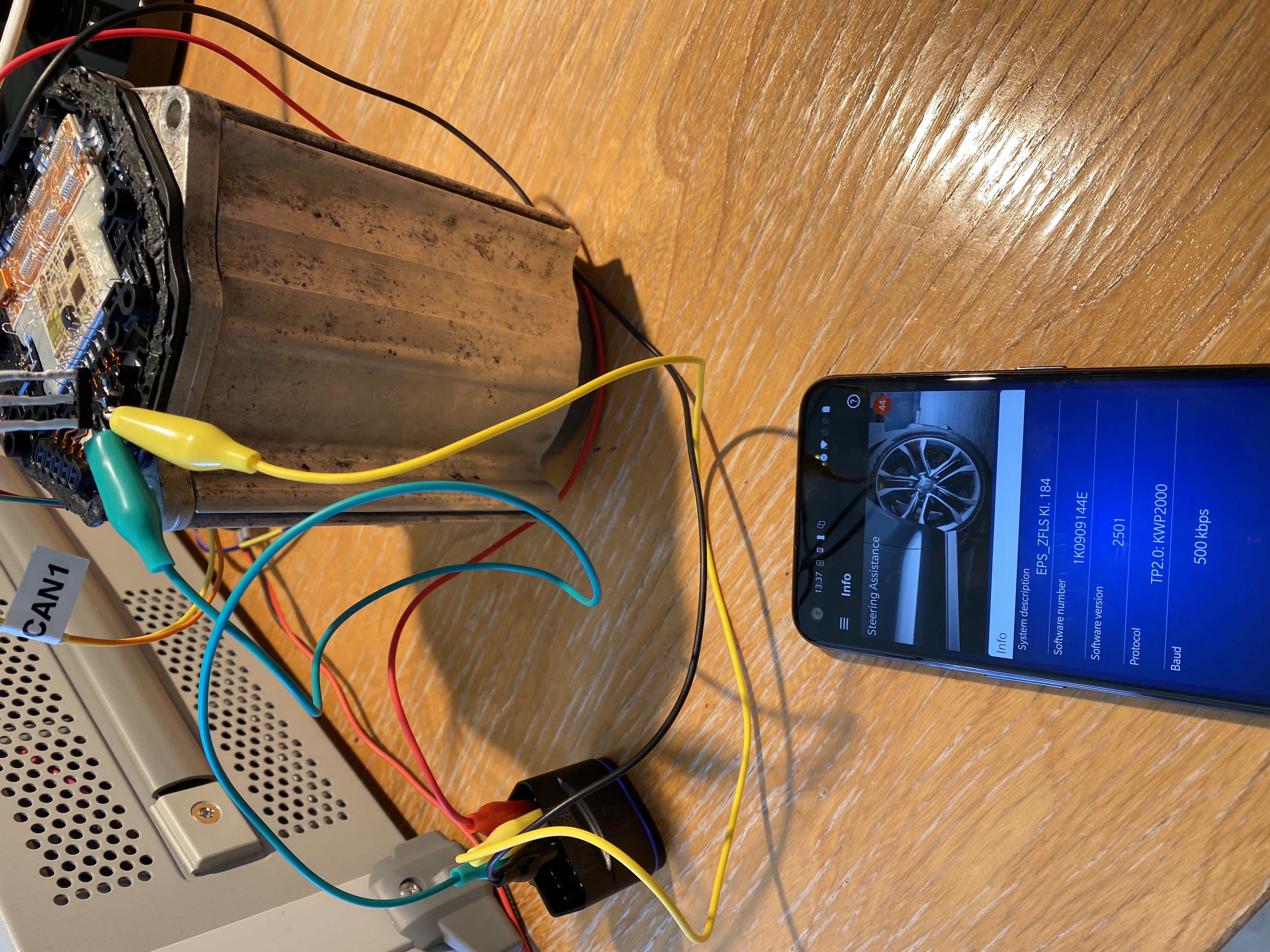
At this point I decided to hook up a commercial VW diagnostics dongle that uses an Android app to talk to the ECU to see what that would turn up. After convincing the dongle to connect (even though most of the car was not present on the CAN bus) it was able to show some diagnostics information about the ECU.
 IMG_3189.HEIC
Volkswagen Transport Protocol 2.0 (TP 2.0)
Now that there is some communication going on I used a panda to sniff the CAN traffic. This yielded us the following traffic:
time     address  data
0.339    0x200    b'09c00010000301'   # dongle - Request channel open
0.342    0x209    b'00d00003a80701'   # ECU    - Channel open response
0.343    0x7a8    b'a00f8aff0aff'     # dongle - Parameter request
0.352    0x300    b'a10f8aff4aff'     # ECU.   - Parameter response
0.407    0x7a8    b'1000021089'       # dongle - 0x10 0x89 - Enter diagnostics mode 0x89
0.412    0x300    b'b1'               # ECU    - ACK
0.422    0x300    b'1000025089'       # ECU    - 0x50 0x89 - Mode 0x89 entered
0.425    0x7a8    b'b1'               # dongle - ACK
0.587    0x7a8    b'1100021089'       # dongle - 0x10 0x89 - Enter diagnostics mode 0x89
0.592    0x300    b'b2'               # ECU    - ACK
0.602    0x300    b'1100025089'       # ECU    - 0x50 0x89 - Mode 0x89 entered
0.605    0x7a8    b'b2'               # dongle - ACK
0.643    0x7a8    b'1200021a9b'       # dongle - 0x1a 0x9b - Ecu identification
0.652    0x300    b'b3'               # ECU - ACK
0.662    0x300    b'2200305a9b314b30' # ECU - "Z.1K0"
0.672    0x300    b'2339303931343445' # ECU - "909144E"
0.682    0x300    b'2420203235303100' # ECU - "  2501."
0.692    0x300    b'2500000000064016' # ECU - ".....@."
0.702    0x300    b'26054d4550535f5a' # ECU - ".MEPS_Z"
0.712    0x300    b'27464c53204b6c2e' # ECU - "FLS Kl."
0.722    0x300    b'2820313834202020' # ECU - " 184.  "
0.732    0x300    b'1920'             # ECU - " "
0.735    0x7a8    b'ba'               # dongle - ACK
You can see a single message being exchanged on the 0x200-0x209 pair, then communication resumes on 0x7a8 and 0x300. A quick google search gives that this must be Volkswagen Transport Protocol 2.0 (TP 2.0). There is not a lot of information out there, but enough to understand what's going on and decode the snippet above.
We can see a channel being opened with module 0x9. Then we see 0x10 0x89, which enters a diagnostic session using KWP2000. Then the app request ecu identification using 0x1a 0x9b, with Z.1K0909144E 2501......@..MEPS_ZFLS Kl. 184 as response (which matches what we see in the app in the previous picture).
Now that we know what protocol is used I can write my own implementation in Python. This GitHub repository contains all the code used in this project in case you also have an ecu on your desk and want to play along at home. I implemented the TP 2.0 transport layer, and some useful KWP2000 services. This will be used in further parts to do some more diagnostics and eventually reflash the ECU.
To conclude the first part of this series, I described my goal (modifying the firmware running on this EPS), got a second copy of the ECU running on my desk, and established communication with it over a standardized diagnostics protocol (KWP2000). The next step in this project would be obtaining (part) of the firmware running on the ECU. The story continues in Part 2.
All posts in this series:
- Part 1: Introduction and Diagnostic communications
- Part 2: Obtaining the application firmware
- Part 3: Reverse engineering and identifying the patches
- Part 4: Obtaining the bootloader and flashing the patches
Footnotes
- Having a copy of the ECU on your desk makes the process much more practical. You can solder wires to it and run (long) experiments without having to sit in the car. Once you get to the flashing part it's also nice to develop and test this procedure on a desk ECU without risking not being able to drive to work the next day because you bricked your car. You wouldn't be the first... ↩
- When looking for an EPS module online you might have to use the term "Steering Pump" even though there are no hydraulics involved anymore ↩
- You'd think manufacturers turn this off, but more often than not JTAG or other debug interfaces were still enabled. ↩
- These are usually labeled using their automotive part number (e.g. SC6676...) but can be traced back to the original part number by looking for the "step" which is below the part number on the chip. ↩