Hacking a VW Golf Power Steering ECU - Part 3
Introduction
This is the third part in this blog series on attempting to modify the firmware running on an Electronic Power Steering (EPS) ECU from a 2010 Volkswagen Golf. The goal is to modify the firmware to remove a 6 minute lockout on lane keep operation and allow use of lane keep at low speeds.
In the previous part I extracted the application part of the firmware from an update file, and loaded it up into Ghidra. I made some educated guesses on the layout of the memory map. In this part I will describe the reverse engineering of the application, and will identify the changes I need to make to disable the 6 minute timer and minimum speed.
When reverse engineering something like an ELF file, you will start with some things like exported symbols and text/data areas split out. However, when reverse engineering an embedded firmware you have to start completely from scratch. You won't even know if bytes represents data, strings or code, and this is not always obvious. First, I will describe some parts of the firmware that can be identified more easily, and will serve as a starting point to find the areas of interest for our modifications.
In most cases, we are interested in modifying parts of the code that make some reference to wheel speeds or desired Lane Keep Assist (LKAS) torque or mode. These values are usually stored somewhere in a global variable, and updated when a new CAN message containing the relevant data comes in. Therefore, areas of interest in the code can be found by looking at all code that references these speeds or LKAS global variables.
In turn, the location of these global variables can be found by looking at the code that parses the CAN messages related to those quantities. These CAN handlers can be found by looking for the CAN address, making some guesses about what the parsing code looks like, or by finding more low level routines that interact with the CAN driver registers.
CAN Registers
At this point I have a binary with hundreds of unknown functions, and we are looking for a place to start. Like when assembling a jigsaw puzzle, we start with the corner pieces, add the sides and then slowly the whole picture starts coming together.
A good place to start is looking up some of the important hardware registers, such as CAN, in the datasheet and label them in Ghidra. Since Ghidra finds all cross-references to an address it’s easy to then look at all places these addresses are used and work your way up across the layers of abstraction.
When labeling CAN registers, and looking at the code that interacts with them, the most interesting parts are how the receive addresses are set up, and where the data is read and copied to. This allows you to follow the data belonging to a specific CAN message and find the code that parses out the individual fields.
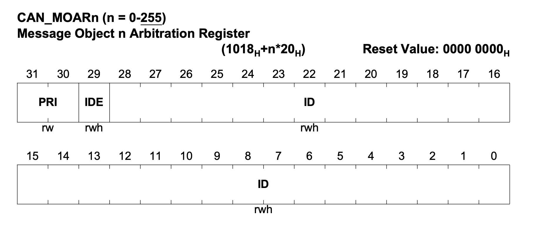
Example register layout for CAN address. Note that this register is repeated every 0x20 bytes for each buffer
The CAN hardware usually has multiple buffers (sometimes called mailboxes) for incoming data. Each buffer can have a filter based on address to ensure a specific message ends up in the right buffer. However, sometimes the messages are sent to a random buffer and later copied to an intermediate storage by an interrupt handler.
Unfortunately I don’t have a datasheet for the microcontroller in this EPS. But since the peripheral region seems to be quite small, maybe I can find the relevant registers using some educated guessing based on the code using the registers.
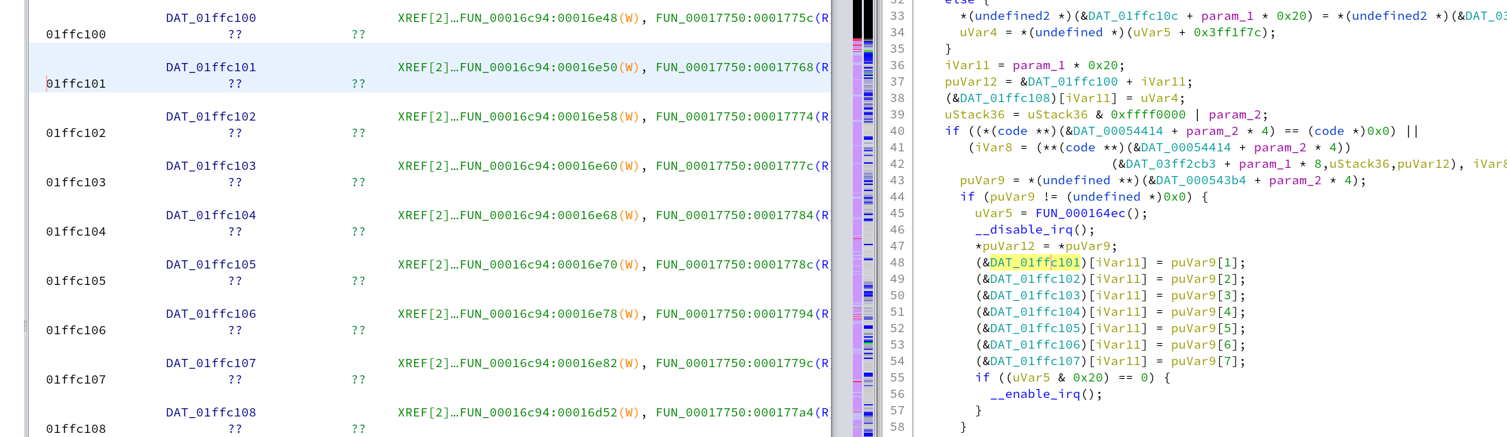
After scrolling through the peripheral areas a bit, I noticed an interesting access pattern around 01ffc100. Here a set of 10 bytes is copied in and out of these addresses as a single block while interrupts are disabled, sometimes with an offset of size N * 0x20, computed onto the base address of 01ffc100. There is a good chance these are registers related to CAN and the 10 bytes consist of 8 data bytes and some information about the size and address of the packet. The functions referencing these addresses would be one of the first places I would start looking when reverse engineering.
I tried to look through some existing Renesas V850 datasheets to see if any of the CAN registers I found match, but didn't find any hits. Let me know I missed something and you recognize the specific type of V850!
CAN Parsing
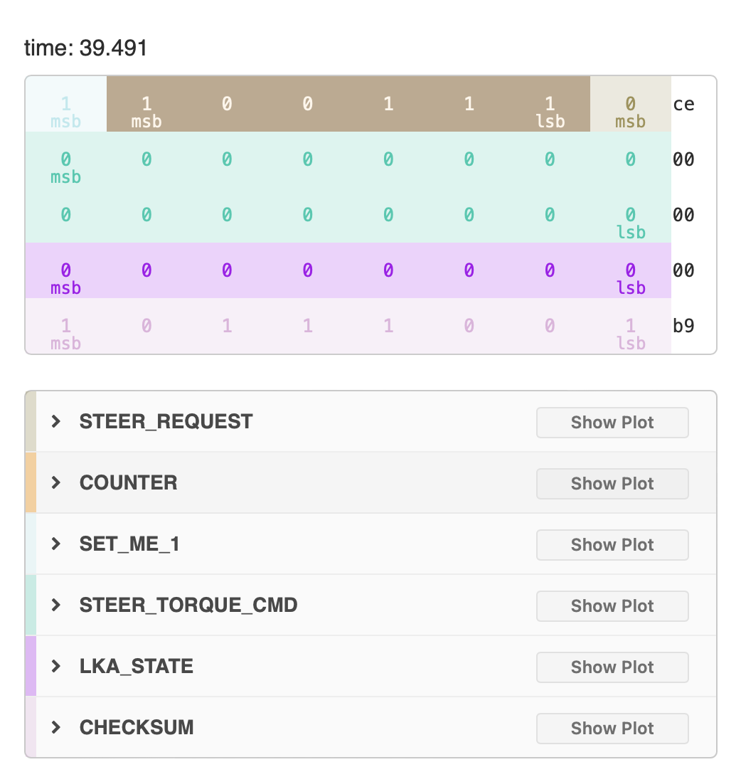
The next step would be to find the code that actually parses the CAN messages, and find the global variables where useful values such as speed of the car are stored. At this point it’s useful to reference the DBC file for the specific car and see how the messages are laid out. I always get confused when just looking at the start and stop bit, and usually load a drive into cabana which will show using colours how the values are placed in the message.
In most cases, the functions handling the CAN parsing are called from a table that contains the address (or mailbox number), intermediate copy of the data, and a callback function to actually parse the data. This table is often referenced by the code interacting with the low-level CAN registers. If you get lucky, it also contains the actual CAN addresses of the messages and you can find it by just searching for the constants.
Unfortunately, looking for constants didn’t work this time as the address in the table were shifted. I found them based on the CAN base register I found earlier (0x01ffc100). Ghidra didn’t automatically find all references, since some of them are computed indirectly. In this case you look for the constant using Search → Memory. Another trick that works well is using the decompiler output. Using File → Export Program → C/C++ you can create a single c file with all the functions decompiled, which can be searched using your favourite text editor.
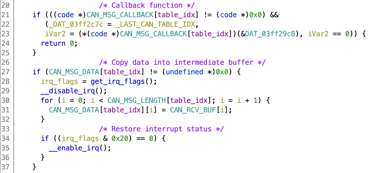
Both methods resulted in an interesting function at 0x0001728c, that uses the CAN base register to compute an offset and store it in an intermediate global variable. Then it calls 0x000171b4 that references some interesting tables. It looks up the length, copies the data from the CAN register into an address from the table. It also has checks for the presence of a callback function, and calls that if it’s not null. Very promising!
Above these three tables we find another table that contains the addresses. Not essential, but it makes things a lot easier since I now also know which memory address/callback function belongs to which address. The addresses are not immediately obvious since they are shifted by two. You can deduce this since values from the CAN registers are anded with 0x1ffc before comparing with values from the table, since the bottom two bits are probably used as some kind of status flag.
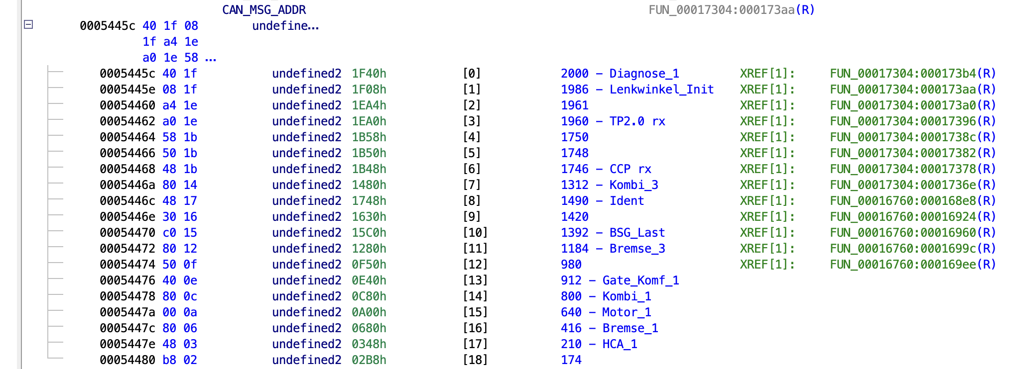
Now using the index of the address table we can find the address of the intermediate buffer, which is referenced by the parsing code. If you can’t find these tables straight away, another method is to look for patterns of shifts and AND operations in the decompiled code, that will be required to parse out the specific values based on the DBC. With some luck the message parsing code contains some generic functions to verify the counter and checksum, which will lead you to the other parsing functions. After finding the address of (one of) the parsing functions, you can start looking for tables that contain that address1.
Using these tables and parsing functions I identified the global addresses for HCA_1/HCA_Status (0x03ff32b2), HCA_1/LM_Offset (0x03ff3238), which I’ll be using later to identify the modifications I want to make.
Diagnostics handlers (UDS/KWP2000)
Another useful part of the firmware that I’d like to identify is the diagnostics handler. On all the ECUs I have seen this consist of some kind of table or big function containing calls to functions for each of the individual services (e.g. ReadDataByIdentifier, SecurityAccess, ...). In case of an error these functions usually return the specific UDS/KWP error code, which makes them easy to find.
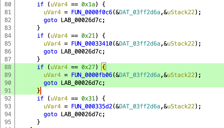
In this case I’ll look through the decompiled code for return 0x35 (invalid key). This gives one hit in the function at 0x0000f820. Following the call stack leads to 0x00026ac8, which contains a big list of if statements, calling handler functions. The invalid key error is returned from the security access handler (0x27), which makes sense.
I won’t go into too much detail of the diagnostic handler. I will note that the flashing functions (requestUpload/requestDownload) are indeed limited in addresses up to 1024 as we noticed earlier. Also the routine controls needed to erase flash are not present. To flash the ECU I need to make use of a bootloader that’s present in address range 0x0 - 0xa000. When reverse engineering KWP/UDS handlers it’s very useful to define enums for the command and error values, that makes it much easier to get an overview of the control flow and error handling of the individual handler functions.
LKAS Checks
With the global variables related to the desired LKAS torque and desired LKAS mode identified we can check where they are referenced in the firmware. HCA_1/LM_Offset (the desired torque) is only used in two places, one function that seems to actually control the steering wheel (if the right LKAS mode is active), and one other function that has a whole bunch of interesting checks (0x00030c46).
Minimum speed
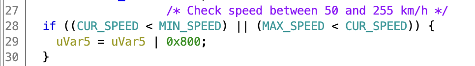
One of the checks in this interesting function compares a number derived from the wheel speeds in the Bremse_3 message, with two constants 50 and 255. If the speed is below 50 km/h, a flag is set which forces the HCA mode into a disabled state. These constants are placed in the vehicle specific calibration map, which also contain car specific torque curves.
Six minute timer
Similar to the speed checks, this function compares two global variables to the constant of 36000 and sets a flag if the value is exceeded. If these variables are timers that increment at a rate of 100 Hz, this would be 360 seconds, or exactly our 6 minute timer!
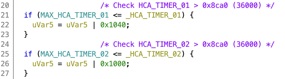
Unfortunately, both the timer and the max value are 16 bit and the check is a smaller or equal comparison. If I would extend the maximum timer value to 0xffff, it would still trigger after about 11 minutes. A different solution is needed to bypass the counter.
Important to note is that after reaching the six minute timeout, you need to stop sending torque and switch to the standby mode for at least one second before the timers are reset. Let’s find this reset logic and 1 second timeout in the code, and see if we can do anything about it.
The only other function that touches HCA_TIMER_01/02 is 0x00030e0e. A part of which is shown below:
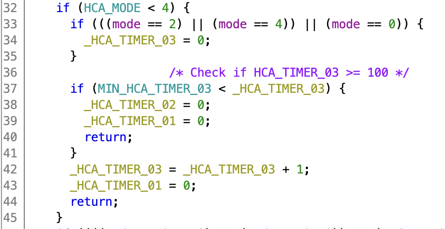
This function exactly implements the observed logic. When entering standby mode (mode 3), HCA_TIMER_03 is reset to zero. While in standby mode HCA_TIMER_01 is set to zero, and HCA_TIMER_03 is incremented. Only when HCA_TIMER_03 reaches 100 (1 second), HCA_TIMER_02 is reset to zero.
Luckily for us this MIN_HCA_TIMER_03 is also in the calibration area. If I change that value to zero, it’s possible to resume normal operation after only 0.01 seconds of standby operation. Interestingly enough this matches the lane keep behaviour on newer VW MQB vehicles. This makes me wonder if that runs a similar code, just with different configuration.
Desired Patches
After all this work reverse engineering the firmware, I have identified the relatively small changes I need to make. MIN_SPEED (0x0005e283) needs to be changed from 50 km/h (0x32) to 0 km/h, which is stored in a single byte. Also MIN_HCA_TIMER_03 (0x0005e221) needs to be changed from 1 second (0x64) to zero, this is also a single byte.
The firmware for this EPS is re-used across multiple cars, and after flashing a car specific steering map is loaded. For the 2501 firmware this map lives in flash between 0x5e000 and 0x5efff. Interestingly both these values live in this vehicle specific area, so maybe Volkswagen had the intention to ship different configurations to different models or model years.
Since this relatively small area can be flashed independently, it should make applying the patches pretty fast. I also checked that these addresses are only referenced once in this function, and that there are no unintended side effects to changing them. If you try this on an actual car, go over the disassembly and verify this for yourself!
Recompute Checksums
In most ECU firmwares I reverse engineered, data blocks are usually accompanied by a checksum to check for data corruption. These checksums are checked on boot-up or periodically. If a mismatch in the checksum is detected the ECU goes into a mode of reduced operation (i.e. limp mode). It still boots into the regular application, outputs CAN messages, and responds to diagnostics messages. However, power steering will be disabled and a warning light will be shown on the dashboard.
When making changes to data blocks you have to ensure all relevant checksums are also updated. This checksum usually lives at the beginning or end of the data block, and is probably some form of CRC. The checksums can be found by looking at references to values at the beginning/end of the block, or by finding the checksum function and looking at the ranges it operates on.
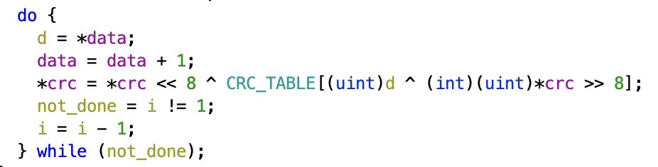
Since most checksums use some form of XOR you can search the decompiled output for ^ and you can usually tell pretty quickly if the function is computing a checksum. Alternatively the checksum function might make use of CRC instructions in the instruction set, these can also be found by using the instruction finder in Ghidra.
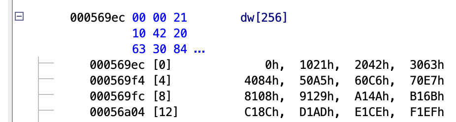
In this case the checksum function can be found at 0x0003def8. And is used to compute a checksum from 0x5e000 to 0x5effb(inclusive). The checksum itself is stored at 0x5effc. From the CRC_TABLE we can see that the polynomial is 0x1021, and the initial value seems to be zero, making this a CRC16-XMODEM. This can be verified by computing the CRC of the data from the dump and making sure the result matched the checksum in the firmware.
Conclusion
In this post I reverse engineered the application part of the firmware. I found the CAN parsing logic, and used this to identify global variables relevant to lane keeping operation. Using cross-references to these global variables I was able to identify the function implementing the checks I want to patch. Both checks can be bypassed using data only changes in the calibration area. Being able to do this using data patches only is much nicer than using code patches. Messing up a code patch usually leaves the ECU in a bricked state, or can have unintended consequences that aren’t immediately noticeable (e.g. overflows, or sign flip). In Part 4 I’ll describe how I reverse engineered the flashing process, and will actually apply the discussed patches.
All posts in this series:
- Part 1: Introduction and Diagnostic communications
- Part 2: Obtaining the application firmware
- Part 3: Reverse engineering and identifying the patches
- Part 4: Obtaining the bootloader and flashing the patches
Footnotes
- Interestingly the 3501 FW for this EPS contained generic checksum/counter functions, but the 2501 functions had these inlined into the actual parsing code. ↩